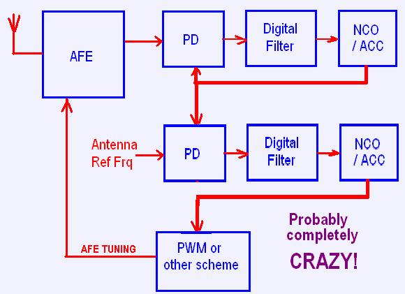
"Since you are driving the antenna directly with a fixed frequency, you don't need any kind of feedback other than phase information to tune the tank L or C. If you go tankless you can only change the L." - Dewster
Hi Dewster,
(I too, am spit-balling without a net, there be crazy talk here):
I am feeling really slow today, just spent the last 1/2 (0.5 LOL) hour trying to explain fractions / decimals to my 8 year old daughter, and getting confused - My 9 year old son (who is absolutely brilliant with maths - calculates quite complex sums mentally far quicker than me - and also beats me at chess ) butted in and explained it all to us both, LOL ;-)..
Ok - not really sure I understand what you are saying.. I think you are suggesting not having the oscillator configured as an oscillator, but have it as a resonator driven with a fixed frequency (MO), and using whatever tuning mechanism to keep this resonator tuned to the MO frequency - as in, as the resonator frequency tries to change when capacitance changes, the PD pulls it back to MO by retuning it (changing L or C).
This does look like a sensible direct was to achieve what I want (an error voltage proportional to capacitance).. Often, however, one makes ones choices based on past expieriences - and I had great difficulty with this approach when I originally tried it on Epsilon (4 fixed frequency antennas).. I now know that I didnt know what I was doing back then ;-).. But the fear remains! - I switched to using a simple driven resonator and amplitude (AM) detection on the antenna - a scheme I still use for volume, driving this resonator from the reference oscillator or multiple thereof in a conventional theremin design.
The thing I really like about the oscillator scheme is that this design automatically 'locates' the resonant frequency - it sort of has two control loops, one being (if tuning wasnt automated) a free running oscillator at the resonant frequency, the other being the PD which tunes the resonator to the MO frequency - it just "feels" safer and easier to me for an analogue system to operate like this.. I can, however, see that for a digital system, driving the resonator with a fixed frequency and simply looking at the phase is probably easier... It may well be easier to do this in analogue as well - but having had the error voltage shoot off in the wrong direction, never to return, because something pushed the PD onto the wrong path, has kind of put me off this approach.
"It would be nice if you could change the L linearly, so as to use the error as an output. I wonder if you could use high speed PWM to switch in / out a small section of winding in a tankless design? Or variably saturate the 6300 with another winding?"
Those switching ideas are interesting - Really interesting - Not fond of using the 6300 as a saturable reactor though - they are a lot of hassle... Fine in a parallel topology where one can pass DC through the main winding without having to choke this, but too much hassle in a series config..
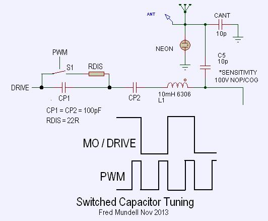
But the switching scheme - hmmm... I wonder if the PWM was at the same frequency as the MO (or perhaps twice this, so each 1/2 cycle got the same treatment)..
In fact, probably dont need to tap the inductor.. just have two series capacitors on the drive side, and switch between these - effectively altering the 'C' component of the total LC .. Just ran this crudely on the sim, and it looks awesome - adding almost any control range one wants (make the C's too small and output amplitude is impacted - but I got 10kHz tunability easily with sensible sized caps) * should just emphasise that this was extremely crude simulation which didnt implement the PWM - I just substituted capacitor values calculated as if I was PWM'ing.
Anyway - no more for tonight.. Ive spent far too much time and have a pile of legal letters I have been avoiding, but if I delay any longer could end up even deeper in brown sticky stuff!
Fred.


