Dear Dewster and FredM
First of all, thank you for the solid theoretical basis that you have carefully explained, in your (almost 500!) posts. Reading them carefully, have helped us, to better focus the problem and the possible solutions.
We're doing experiments, and collecting the results in a very detailed PDF file. It is about twenty pages long, one for each technique and any aspect, from the antenna, to the pitching coil and the oscillator, all accompanied by calculations, advantages and disadvantages.
It still will take some time to be reasonably detailed before you read it. Would be great, having you help with a review, corrections and additions.
Given that it may take weeks yet, I have an anticipation that could (possibly) be useful to Dewster, for his FPGA .
-------------------
Obtaining heterodining with sampling
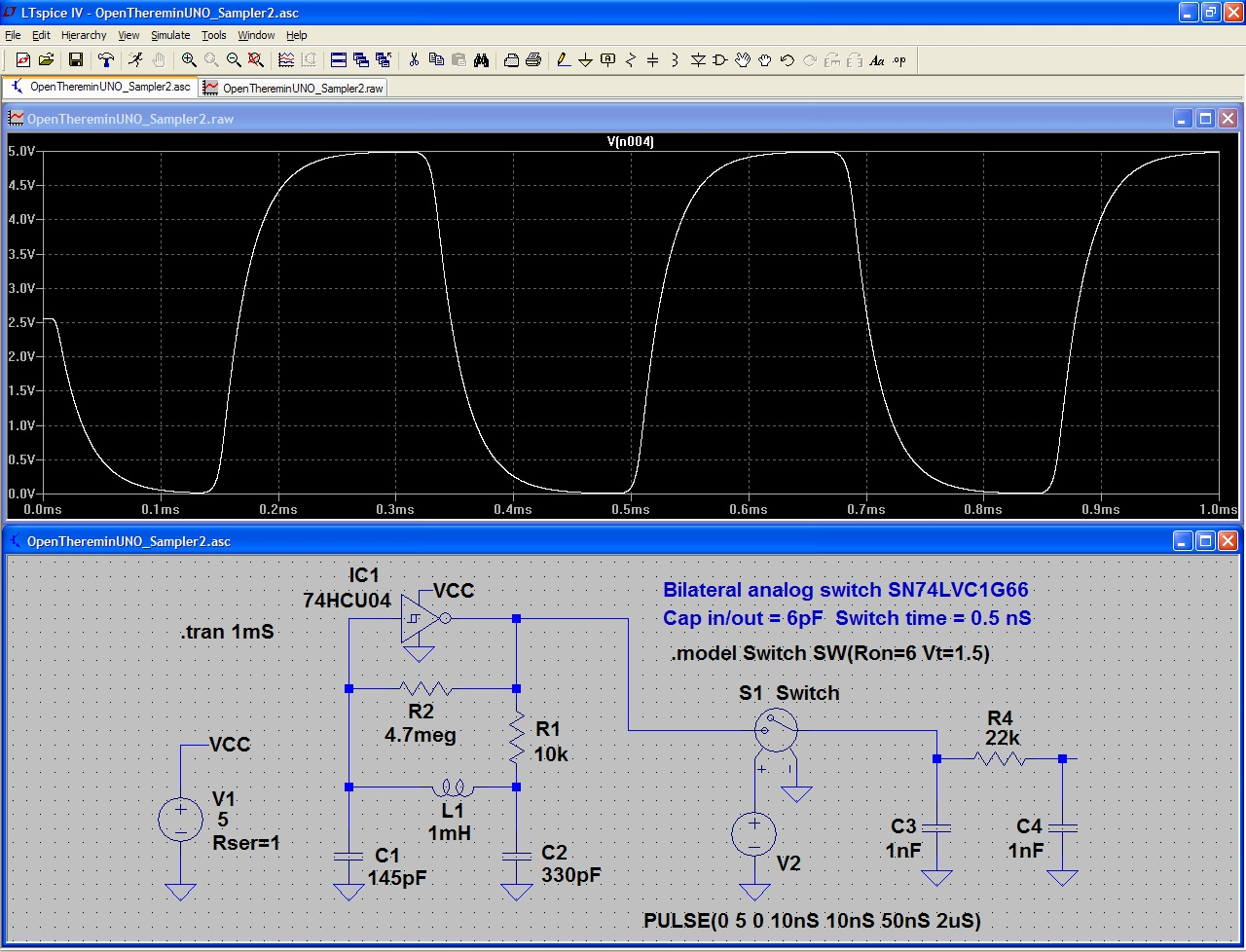
For this technique, an ADC it's not needed, nor starting the process from a sine wave, instead proceed as shown, in the following simulation:

1 ) We start from a square wave, to avoid being forced to derive the signal from the oscillator circuit. Same as the balance wheel on a good clock, that must be isolated from any influence (some were even built in vacuum), also a good oscillating circuit must be, as much as possible, isolated from the circuit components, that change their capacity with temperature.
2) Instead of using an ADC (which would limit the maximum frequency at around 300 - 500KHz) we use only a Sample-Hold. This way you can rise the frequency at will, to take advantage of small coils, that are stable and with low parallel capacity.
3) A short sample time of about 100 nS (to be adapted to the components and the frequency used) facilitates the subsequent integration given by the low pass filter.
4 ) We add a light filtering, two poles are enough because the 300KHz component to be eliminated, is already very attenuated by the fact that sampling is used, instead of XOR.
5 ) The final signal is already quite large and steep, as to be read directly by a schmitt trigger. For this reason, over the operational circuit of the low pass filter, the squaring components are eliminated, too.
For those wishing to experiment with a hardware sample and hold, the ideal component is the Bilateral Switch, shown in these simulations. Its incredibly short reaction times (a few nano seconds), allow you to rise the frequency as necessary and precisely sampling, regardless of the timing of ON and OFF.

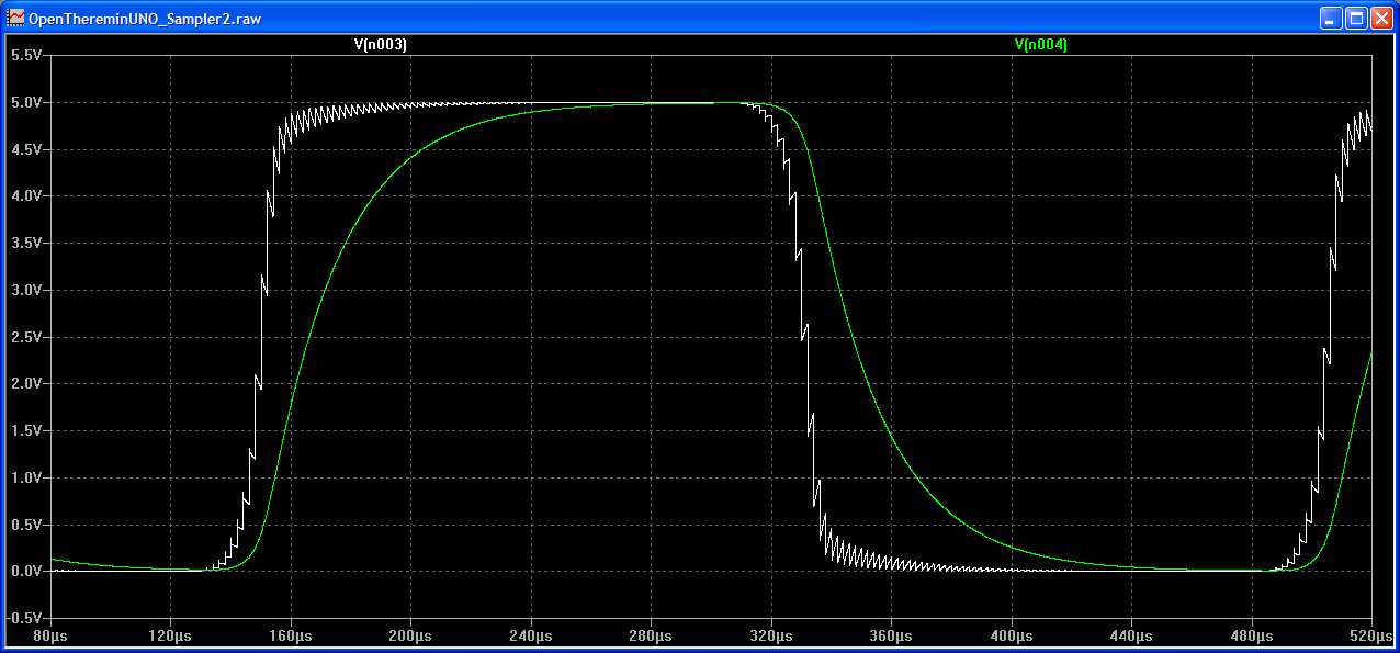
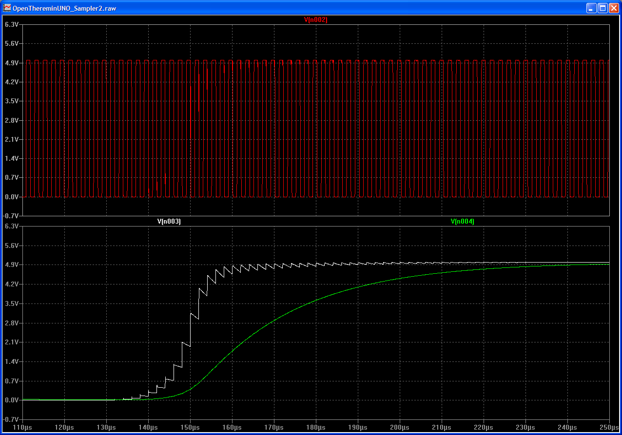
As you can see in this picture, two passive lowpass cells are sufficient. If neeeded, filtering can be increased further by lowering their cut-off frequency.

RED = oscillator
WHITE = voltage on sampling capacitor (Note 1)
GREEN = voltage on second low pass cell
(Note 1) The first sampling capacitor, the "bilateral switch" ON resistance and the very short sample time, are all working together to implement the first low pass cell.

