Been playing with oscillators, the Clapp adapted for Theremin use, and livio's Colpitts used in his CapSensor Theremino. This Clapp is currently running on my bench:

I'm using the split counter-wound tank inductor, and placed some capacitance to ground at the split point (C4). This obviously cuts into the sensitivity, but it seems to increase stability more than it reduces sensitivity, but I don't have hard numbers to back this up, or any theories.
Some LTSpice waves:

Antenna voltage (for a 5pF antenna) is around 32V peak (64V p-p).

Output of the buffer. Rise time is around 50ns which should be fine for the FPGA. Seeing ~100ns in the working circuit, it turns into more or less a sine wave if you grasp the antenna.
Took me over a day of studying, simulating, and benching to settle on using livio's simple but efficient NPN buffer, but with 1/10 the collector resistance. I wanted to use a FET here but nothing I tried worked as well as a BJT.
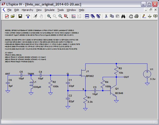
Here is livio's CapSensor Colpitts oscillator for comparison:

After simulating it and changing stuff around I'm not sure why C1 doesn't equal C2. Also, low bias current (set by R1) is desirable in LFOs to minimize flicker noise and self-heating, but for Theremin use if the bias is set too low there isn't enough energy to overcome tank losses, particularly when a hand touches or grasps the antenna, and particularly when the antenna swing voltage is set rather high, which can produce a stall (which both recover from). With the tapped split inductor with 10pF to ground and R1=1k I don't see stalling on my oscillator when grasping the antenna (though I do see obvious signs of reduced antenna voltage when it is grasped).
Surprisingly (or not), livio's oscillator can be modified to do very similar voltage swings as those in the adapted Clapp, but not quite as high. And it can be configured to have very similar sensitivity to the Clapp, but again not quite as high.
If you replace R1 with a FET constant current source and vary the current by changing the set resistor, you can fairly linearly vary frequency. I don't see this very strongly in simulation, but the bench circuit increases ~1400ppm by lowering R1 to 500 ohms. This might be a good mechanism to offset any temperature / frequency drift with one or two thermistors.
============
I'm using a new sensitivity metric. It is (%F change) / (%C change). To find the maximum or ideal: For a 10pF antenna + 1pF hand, since LC frequency is proportional to the inverse of the square root of the capacitance, we have:
%F change = [(11^-2) - (10^-2)] / (10^-2) = -0.04654 = -4.654%
%C change = [11 - 10] / 10 = 0.1 = 10%
%F / %C = 4.654 / 10 = 0.4654 = %F/%C MTS (Maximum Theoretical Sensitivity)
So sensitivity can (and will here) be stated in terms of MTS, from 0 to 1.
============
0. livio's Colpitts gives 32V p-p at the antenna and 0.28 MTS.
1. Removing the 18pF C5 from livio's circuit yields 40V p-p and 0.42 MTS.
2. Further modifying (1) so C1=C2=220pF and R1=1k yields 80V p-p and 0.36 MTS.
============
By contrast, my Clapp as show above has 64V p-p at the antenna and 0.49 MTS.
Reducing C4 to 4.7pF yields 96V p-p and 0.72 MTS.
Eliminating C4 gives 145V p-p and 0.96 MTS. And increased instability.
Bear in mind that my circuit uses a somewhat inferior FET, if I were to use livio's FET the antenna swing would go up ~25%. Also note that the above are calculations done from spice data, not actual circuits, and that all inductors were treated as ideal.
I haven't breadboarded livio's Colpitts, for all I know it is more stable than the adapted Clapp. But I don't really like the look of C4=10pF tank drive & sense, but perhaps that's irrational.
============
I'm coming to the conclusion that I'm a moron for doing any kind of temperature testing with circuits on a bread board. Need to do an ugly construction or similar oscillator and give that some time in the freezer.
============
[EDIT] Spice here: http://www.mediafire.com/download/8dy1d2iakxakxda/osc_clapp_livio_2014-03-21.zip


