Let's Design and Build a (mostly) Digital Theremin!

Posted: 5/31/2014 12:14:41 PM
dewster

From: Northern NJ, USA

Joined: 2/17/2012

"Do you know of any nice TH packaged push-pull drivers? I have used Micrel MOSFET drivers in the past, and am looking at the Microchip TC4469 http://ww1.microchip.com/downloads/en/DeviceDoc/21425C.pdf"  - FredM

Afraid not, though those parts look interesting.  I wasn't aware they existed.  2KV ESD on all pins. 

So 74HC04 and the like are out?

Posted: 5/31/2014 1:23:57 PM
dewster

From: Northern NJ, USA

Joined: 2/17/2012

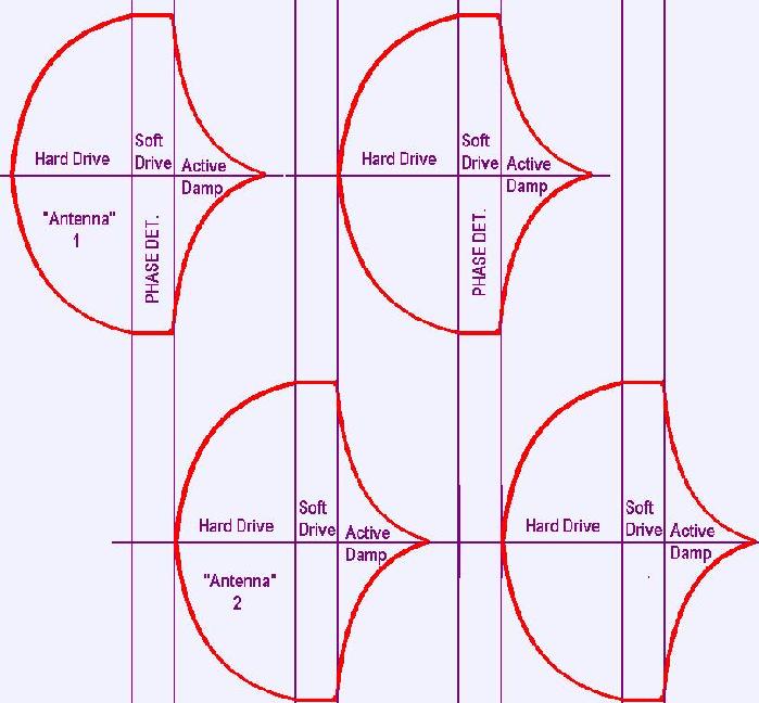
"Thinking that I read the phase a few us after stopping the drive, so that the BPF's natural resonance is detected.. perhaps doing the sequencing / sampling closed-loop so levels are all stable (above / below trip points) when the states are changed (could also actively damp the resonator after phase data is collected, to speed up the operation)"  - FredM

Back seat driver: I would try driving the series LC hard through a relatively small resistance and look for what would nominally be quadrature (90 degree shift).  This would maybe get the voltage swing up faster and give you more time to sample phase (though you could likely begin sampling it before hitting max Vp-p).  The envelopes might look more RC-ish rather than sine-ish.  To get phase shift I would sample while driving rather than letting it go - you aren't interested so much in the natural frequency, but the I/O phase transfer function.  Driving with some non-resonant ratio of frequency / phase for a bit might work to kill oscillation - or you might somehow do three level stimulus and cut back the duty cycle so as to reduce the oscillation voltage without completely killing it?  I'd initially try for as large a phase sampling time (as a ratio of total time) as possible, unless a good reason cropped up not to do so.  Most / all of the above might be fairly easy given an FPGA in the design.

Posted: 5/31/2014 2:41:35 PM
FredM

From: Eastleigh, Hampshire, U.K. ................................... Fred Mundell. ................................... Electronics Engineer. (Primarily Analogue) .. CV Synths 1974-1980 .. Theremin developer 2007 to present .. soon to be Developing / Trading as WaveCrafter.com . ...................................

Joined: 12/7/2007

Hi Dewster,

Thanks for your input - real helpful! ... Yeah, the attack /decay curves of the oscillations are much more RC like - but I had that image for something else and just adapted it for quickness - lots of other things are "wrong" with the diagram as well.

"To get phase shift I would sample while driving rather than letting it go - you aren't interested so much in the natural frequency, but the I/O phase transfer function. "

True - and I can see this now ive simulated - letting go really doesnt work.

"or you might somehow do three level stimulus and cut back the duty cycle so as to reduce the oscillation voltage without completely killing it?"

Really great idea! - drive hard to get the levels quickly, then drop back to a gentler drive for phase sampling, then damp the oscillations (switch a resistor across the antenna - damp +Ve 1/2 cycles with a MOSFET) when removing the drive - I can speed up the sequencing greatly by doing this..

I hope I dont need to do any of the above, and can just get away with continuous drive - Have managed with some prior stuff.. But they were less demanding and I was less pedantic then..

One slight worry about the above is the nature of radiated emissions - I suspect that bursts of say 500kHz "carrier" at say 20kHz  would be potentially more disruptive than a continuous 500kHz or slowly changing frequency from conventional theremins - I think the best would be an un-modulated 500kHz "carrier" with only slight slow (sub audio from hand movement) amplitude modulation - the worst could be the AM pulsed signal the above proposal could produce.. this is one reason I would want to overlap the antenna signals a bit.

" I'd initially try for as large a phase sampling time (as a ratio of total time) as possible, unless a good reason cropped up not to do so. "

I only need one phase pulse - but perhaps taking a load and averaging the value is a good idea... I am using a fast RC integrator into a SAH to convert the width of the phase pulse into a voltage - and hoping to use the exponential curve of the voltage - time to do part of the linearizing function..  But I could repeat this process during each burst and average the results in a seperate integrator, but I cant use a single integrator in the usual PWM manner if I want to exploit the RC (charge) exponential function.


Fred.

updated diag:


Posted: 6/1/2014 12:47:17 AM
dewster

From: Northern NJ, USA

Joined: 2/17/2012

From telephony / communications, there are many ways to share a medium:

FDMA - Frequency Division Multiple Access - transmit on different frequencies

TDMA - Time Division Multiple Access - transmit on the same frequency taking turns

CDMA - Code Division Multiple Access - transmit on the same frequency using different orthogonal codes (Gold codes) and maintain roughly equal amplitudes at the receiver.

When doing TDMA you could actually do FDMA as well.  That is, adapt the stimulus frequency to the resonance of the given tank.  You could do this upside down (a given fixed frequency for the given tank and look at phase) or with variable frequency tracking resonance (start with the frequency from the previous cycle for that tank and follow the phase in this cycle - i.e. intermittent PLL).

Posted: 6/1/2014 1:40:32 AM
FredM

From: Eastleigh, Hampshire, U.K. ................................... Fred Mundell. ................................... Electronics Engineer. (Primarily Analogue) .. CV Synths 1974-1980 .. Theremin developer 2007 to present .. soon to be Developing / Trading as WaveCrafter.com . ...................................

Joined: 12/7/2007

Hi Dewster,

"So 74HC04 and the like are out?" - Dewster

Not sure - If I can get my BPF sharp enough (and fast enough) without pumping loads of start-up current and requiring low drive resistance, then perhaps not.. But I  need to use all 6 inverters (parallel) for my present scheme, and thats running above my preferred 50% of the device spec..  and if I can get 4 drives running well within their rating and not getting warm, from one package, id prefer that - and  board area would be reduced. I just thought there might be some neat part I didnt know about ;-)

----------------

I probably shouldnt be discussing this on your digital theremin thread I suppose - its kind of digital related (certainly a lot could probably be implemented easier in digital) - But I am still looking at using this stuff for an analogue heterodyning theremin - and in this context, only something like TDMA is really applicable..

But there are a lot of factors which might be common to both digital and my analogue "upside down" topologies - we both need to detect at least two antennas, we are both looking for phase difference .. Where the two diverge sharply is that with digital you are free to employ any of the "ways to share a medium" you list above/

<not about digital>

I have a strong aversion to (fear of ?) having multiple asynchronous HF oscillators in the same environment - this is particularly horrible IMO when one is deliberately beating two of them to produce audio - Ok - this works with conventional theremins because the volume oscillator is tuned so as not to interfere with the reference or VFO frequencies.. But I still dont like it! ;-)

My proposed solution is to have everything locked to a reference oscillator (even have an on-board SMPS locked to it) and have one VFO which when heterodyned with this reference produces the audio - that way, any unintended interactions or 'leakages' can only produce the intended audio frequency - no ghosts - no fiddling with other oscillator frequencies to get things right..

Of course, digital solves all these (real or imagined) problems - because the front-end is purely a detector and has no components which are actually or directly used to produce audio.. It IS the most sensible way to go - divorce the sensor and the sound engine and only let them talk via a solicitor, LOL ;-) [the front-end is most definitely the wife - quirky, troublesome, and does most, if not all of the talking...]  But this route does have some other costs..

I could do similar (and was going that direction) in analogue - separate front-end outputting CV's, and separate reference and VCO to produce heterodyned audio.. But it just seemed wasteful to duplicate the reference, and also added another level potential drift problems - and this spawned the "upside down" topology...

This latest is a variant of that, where instead of using PLLs to lock  VFOs to a reference frequency (the original idea) and use the error signal to drive a HF VCO' to heterodyne with the reference, and to drive a VCA, I am looking to instead directly obtain the "error" by phase comparison.

I thought this latest variant would be simpler (and safer, as it gives the option of switching antenna drives) - but im starting to wonder..

Really, the choice I had was to do the above, or to abandon heterodyning the audio and just drive a voltage controlled synth (as I believe Moog did with the 91).. I can see why Bob went the way he did! -

But as I say - I can see that this discussion probably shouldnt be on this thread - so I will leave it .. I may start a new thread, and would be fine about moving this post there... I think im in a funny head-space right now, and babbling without thinking things through -  PLEASE ... (and this is to everyone) Just let me know if I am OT/OTT and I will move ;-)

Fred.

Posted: 6/1/2014 1:55:22 PM
dewster

From: Northern NJ, USA

Joined: 2/17/2012

"I just thought there might be some neat part I didnt know about ;-)"  - FredM

Neat parts no one knows about seems to be your department.  :-)

"I have a strong aversion to (fear of ?) having multiple asynchronous HF oscillators in the same environment - this is particularly horrible IMO when one is deliberately beating two of them to produce audio - Ok - this works with conventional theremins because the volume oscillator is tuned so as not to interfere with the reference or VFO frequencies.. But I still dont like it! ;-)"

I have this exact same feeling / aversion / fear.  Sticking two or more exquisitely sensitive circuits right next to each other seems like asking for it.  Prototyping may not necessarily "prove" a design because of the various EM, grounding, etc. environments it may find itself working in.   My brain sees one crummy FET doing so much, it's working overtime in the background trying any & every fancier and more promising seeming approach that comes down the pike.

"My proposed solution is to have everything locked to a reference oscillator (even have an on-board SMPS locked to it) and have one VFO which when heterodyned with this reference produces the audio - that way, any unintended interactions or 'leakages' can only produce the intended audio frequency - no ghosts - no fiddling with other oscillator frequencies to get things right.."

The Open.Theremin uses one Xtal with divide by 7 and 8 for the references.  I wonder if there is any non-interference magic to be gained by doing that?

Posted: 6/8/2014 5:15:17 PM
dewster

From: Northern NJ, USA

Joined: 2/17/2012

Hive processor core updated to v05.03:

Design document: http://www.mediafire.com/download/1tjszeo0kmy14ym/Hive_Design_2014-06-07.pdf

Excel simulator: http://www.mediafire.com/download/ypii57k6c6z713h/HIVE_SIM_2014-06-08.xls

Verilog code: http://www.mediafire.com/download/1niwno3c2ncnbxq/HIVE_2014-06-07_v05.03.zip

New logic to improve interrupt support, 32 bit register access, a fair amount of rewrite to facilitate verification (and to scratch my seemingly endless need to rewrite code itch).  I tried to make memory read/write 32 bits wide but that unfortunately broke the way I enter boot code using the verilog initial construct.  Ah well. 

Hitting the diminishing returns wall with Hive editing, which means it's either close to "done" or I'm just running out of ideas. Anyway, I'm quite pleased with how it's turned out.  After bajillions of hours of pondering all things processor I have something decent to show for it.

Posted: 6/9/2014 3:56:14 PM
FredM

From: Eastleigh, Hampshire, U.K. ................................... Fred Mundell. ................................... Electronics Engineer. (Primarily Analogue) .. CV Synths 1974-1980 .. Theremin developer 2007 to present .. soon to be Developing / Trading as WaveCrafter.com . ...................................

Joined: 12/7/2007

Dewster,

[probably worth ignoring the the fo;;owing - I have just downloaded the 53 page manual!  - Yeah, that's some work you've done!!! - Sure all I ask below will be answered when ive read it! ]

It sounds really impressive!

I know that on forums where core's are the staple diet, how to actually implement and code for Hive is probably comprehensible - but for FPGA and Core illiterates, can I ask some really dumb questions?

One has your FPGA, and have managed to "code" hardware constructs into it with Verilog or whatever (in my case probably schematic entry) .. This "hardware" needs to communicate with a processor of some kind (say one has implemented a phase comparator and your "hardware" wants to send pulses for the MCU to process)..

Presumably one drops in your Hive Verilog processor "module" (or puts this in before linking your hardware constructs) ..

Now you need to route the 'pulses' to an appropriate "port" on the MCU - but this is all inside the FPGA.. So presumably one uses naming #define or whatever..

So you have the processor and hardware linked...

Now, the code... The code for Hive is presumably written in an assembler type manner - ? - If so, is it converted to machine code through an assembler one can obtain or one you have written?

Or is my thinking bog-eyed? Does one actually write the "code" in Verilog and include this with the Hive "module" ?

Here is my area of total braindeadness - I have put systems together using MCUs more times than I can count, but its been an MCU with ports one connects and configures to "hardware" - Ok, the old days when all the hardware was external has long gone - but the principle remains the same - one has PICs with on-chip timers and PWMs etc, and one has the processor independent, and the code mainly says how these internal "peripherals" are configured and "wired".. and does its stuff to control / read "peripherals" (on-chip and off-chip) and act on these actions.. This extended hugely with PSoC where there are loads of digital and analogue peripherals ("User Modules") and user configurable "CPLD" like modules - but with all of these there are defined registers and interfacing APIs ..

With a FPGA one is really designing or implementing everything - For PSoC there is a manual the size of an old telephone directory detailing where things are.. So when taking Hive for example, does one need to specify / create everything ? (Admittedly, with PSoC, one only ever uses << 10% of the dedicated functions / registers in any single application)

Could you simply describe how an engineer would put a FPGA application with Hive? - A simple "hello world" or "I can make a tone that sweeps from 20Hz to 20kHz" - just to get an idea about the processes involved?

All I have done with FPGA is mop up a load of logic functions to produce waveforms using my logic "mixer" - and all this was done using schematic entry (and I cant even get that to work now! ;-)

Fred.

Posted: 6/9/2014 9:26:06 PM
dewster

From: Northern NJ, USA

Joined: 2/17/2012

Hi Fred,

Hive is coded in verilog in a modular way.  Separate *.v files hold the code for various pieces ("modules") and they are pulled together and wired in a hierarchical manner as sub components, which are themselves pulled together wired up as the Hive core at the top level module ("hive_core.v"). 

To use it, one would write an even higher level module that pulls in ("instantiates") the top level module along with other logic and wire them up.  This would likely be written in verilog (mixed HDL projects are supported by FPGA vendor tools but I've never tried it) or via the proprietary schematic capture method in the given tool. 

Here is the top level entity for my Cyclone 4 demo board:

module ep4ce6e22c8_demo_board
    #(
    parameter    integer                            LED_W            = 4
    )
    (
    // clocks & resets
    input         wire                           clk_50m_i,       // clock
    input         wire                           rstn_i,          // async. reset, active low
    //
    output        wire    [LED_W-1:0]               led_o            // LEDs, active low
    );


    /*
    ----------------------
    -- internal signals --
    ----------------------
    */
    wire                    [31:0]                    io_o;
    wire                                              clk_pll;


    pll    pll_inst (
    .inclk0                ( clk_50m_i ),
    .c0                    ( clk_pll )
    );


    hive_core hive_core_inst
    (
    .clk_i                ( clk_pll ),
    .rst_i                ( ~rstn_i ),
    .xsr_i                (  ),  // unused
    .io_i                (  ),  // unused
    .io_o                ( io_o )
    );

    // the LEDs are active low
    assign led_o = ~io_o[3:0];


endmodule

You can see that the Hive core has a rather trivial port interface: clock, reset, interrupts, and GPIO (the UART port isn't shown here).

For this uber entity you would specify pinout in the vendor tool, as well as any timing constraints for the pins and internal logic.  The tool facilitates this to some degree, but you can specify these things with text files as well, and I generally find this to be the easiest route.  For slow I/O like LED outputs, button and encoder inputs, etc. the pin timing can be set to don't care, and the internal timing is largely constrained by telling the tool the input clock frequency you will be supplying (likely through and internal PLL to multiply it up as it is in my above example).

Once that is done you need to program Hive.  The boot code is in a file ("boot_code.v") which initializes main memory.  You would edit this file and rebuild the design, then reprogram the FPGA configuration memory.  At power cycle (or pressing the "config" button on the demo board) the new load is pumped into the FPGA and you're in business.  Boot code is actually written in verilog, and uses some of the language features to make it fairly readable.

For anything other than trivial programs, the Excel simulator is probably the place to develop subroutines and such, but it's a little clunky and kind of slow.  I'm still working on porting the Excel output to a text file, which could then be uploaded to Hive running a boot loader / tiny monitor of sorts.  Some kind of serial memory would be necessary (they can be had for almost nothing) wired to the demo board.  Programming support is something of a missing link for larger projects.

In terms of the things you might bolt onto the Hive core, there is free code out there for a lot of functionality, but who knows what the quality may be like.  At freecores they came up with the "wishbone" standard so as to standardize a register set interface between code and processor.  If your processor core and the additional functionality are both wishbone compliant you can theoretically join them together easily.  I have my own register primitive that the internal register set is constructed with, and prefer to keep this kind of logic in one conceptual spot rather than spattered around the design.  So with Hive you would probably end up writing or at least heavily adapting code for extensions / peripherals.

=============

I've been bumping up against the inherent limitations in verilog (no multi-dimensional ports, no packages) so today I'm working on porting Hive to SystemVerilog.  SV is confusingly named, it's actually an updated version of verilog, with the verilog name going by the wayside.  SV is touted (and used) more as a verification language, but synthesis support is definitely there and a definitely an improvement over verilog.  Surprisingly there is NO support for SV in the Xilinx XST tool!  Altera Quartus seems to support SV pretty well and has done so for quite some time.

Eric

Posted: 6/10/2014 12:57:26 AM
FredM

From: Eastleigh, Hampshire, U.K. ................................... Fred Mundell. ................................... Electronics Engineer. (Primarily Analogue) .. CV Synths 1974-1980 .. Theremin developer 2007 to present .. soon to be Developing / Trading as WaveCrafter.com . ...................................

Joined: 12/7/2007

Thank you for that, Eric.

I think I am probably out of the running on this! ;-)  Or at least I am unless I get a load of money and loads of time.. I think its one of these areas where one probably gets the skills through quite a long focused route (in a "real" development situation / work) or a strong passion and interest  -

But your description does put some of the pieces together a bit - and I am reading through your document (fortunately, a lot was covered in previous documents from you, so its not all new).

I just want to keep up enough that when you bring your theremin to market, I will hopefully be able to at least glimmer what you are doing ;-) ... For me, the real irony is that I may end up using an FPGA simply because of cost - I dont need anything as big as the smallest FPGA available (all I really need as a few PALs/GALS , but they are almost impossible to get at low cost - and the tools for developing / programming them are now unavailable or expensive) so I will probably have an FPGA only 5% used... Its a balancing thing now between FPGA and MACH5 CPLD.. The same FPGA will run your whole machine!

Fred.

You must be logged in to post a reply. Please log in or register for a new account.