Let's Design and Build a (mostly) Digital Theremin!

Posted: 9/25/2014 12:21:32 PM
dewster

From: Northern NJ, USA

Joined: 2/17/2012

Hi Fred,

Thanks!  I'll certainly keep that in mind.

I believe the FPGA RAM resources I'm dealing with are on the same order as the Flash size in the PSoC4.  Cyclone 4 EP4CE6 has 30 x 8kb BRAMs, which gives Hive 8 stacks and a memory depth of 16kB.  Upgrading to the EP4CE10 board ($38 USD) would double the memory depth to 32kB.  In both cases there are 6 BRAMs left over which could certainly be used for display buffer / character ROM if I go that route.

These LCD character-based display products are ancient and clunky and expensive for what you get (from the same site a full-blown color 4.3" TFT w/ SPI interface and touch screen option, character generator, etc. can be had for ~$25!) but I don't see any kind of replacement for them in mid-level complexity projects such as this. 

If they still made high efficiency LED calculator displays for not too much scratch I'd consider going that way.

I suppose I should just order this sleazy 16x4 for $10 and get over myself:

I'm probably coming across as a unappreciative crank with this display issue, but once you let crud creep into your project you'll be dealing with it until you're dead.

Posted: 9/25/2014 4:41:36 PM
FredM

From: Eastleigh, Hampshire, U.K. ................................... Fred Mundell. ................................... Electronics Engineer. (Primarily Analogue) .. CV Synths 1974-1980 .. Theremin developer 2007 to present .. soon to be Developing / Trading as WaveCrafter.com . ...................................

Joined: 12/7/2007

Hi Dewster -

I wasnt suggesting you replace the FPGA/ Hive with a PSoC4 just in case thats what you are thinking.. - My thinking was on the lines of configuring the PSoC as a peripheral component -that this would free up more resources in the most important bit - the FPGA.

If one can buy a lower cost but more 'difficult' LCD, the PSoC could be entirely devoted as an LCD interface, and have enough space to fit whatever LUTs or RAM was required. What are they.. $4? Why waste any of your superb barrel processor (even if its 'spare') on doing a task well beneath it... Who knows, the resources consumed by the LCD might just cause a problem later if you realize/invent some extra 'something' - ... You may just find that you need to create an additional mixed-signal sound engine for example, to complement the wave-table, or choose to implement Gordon's 'ping' ... these are just silly examples - but I have learned from experience that spending a couple of extra £ on something "needless" (particularly with configurable parts like PSoC [or I suspect FPGA]) can pay back hugely not too far down the 'revision' line.

And it may just be that adding some "peripheral" component could actually reduce the cost or be no more expensive..

But only you knows how much 'elbow room' your design has - If its plenty, then the above isn't relevant.

Fred.

Posted: 9/25/2014 9:42:36 PM
dewster

From: Northern NJ, USA

Joined: 2/17/2012

"I wasnt suggesting you replace the FPGA/ Hive with a PSoC4 just in case thats what you are thinking.."  - FredM

Yes, thanks for the clarification but I didn't misunderstand you.  I suppose my rant concerns lack of these kinds of products for intermediate complexity projects.  One doesn't necessarily go from blinking an LED, then immediately to projects that need widescreen touch color TFTs and ARMs with video processors, but that's how the display market seems.  The intermediate displays tend to be dinosaurs, the stuff at either extreme fairly modern.

The display issue has to be resolved, but I think I'm worrying prematurely - development at this point can likely proceed most flexibly via the UART and a terminal emulator rather than via displays and knobs and such.  Am in the process of scraping the HW and SW together to do the initial testing of digital heterodyning and such.

Posted: 9/26/2014 12:41:43 AM
FredM

From: Eastleigh, Hampshire, U.K. ................................... Fred Mundell. ................................... Electronics Engineer. (Primarily Analogue) .. CV Synths 1974-1980 .. Theremin developer 2007 to present .. soon to be Developing / Trading as WaveCrafter.com . ...................................

Joined: 12/7/2007

Hi Dewster,

The user interface side is something I will need to do once I have proven the sensing and primary sound generation board (until then all I can do is edit parameters with the ICE, and this is a right royal pain.. so a basic UI at least is fairly high priority)

Ok, im using PSoC4's for everything so obviously that's my focus - but I thought these might interest you.. A project for PSoC4 and a custom configuration (API's etc) component for driving Nokia graphics displays - The Arduino PSoC4 development board could be replaced with one of the $4 breakout boards.

Project on E14

Color graphics LCD @ $22

Fred.


Posted: 9/26/2014 1:39:19 PM
dewster

From: Northern NJ, USA

Joined: 2/17/2012

Hi Fred,

Thanks for those links!  I must say that I feel a little dumb severely restricting the memory in an audio product like this Theremin project, and for a semi-vanity reason like Hive, but it doesn't seem like a lot is necessary unless one employs large wave tables, lots of audio delay, etc.  Buffering displays, particularly graphical RGB which require many bits per screen pixel, and implementing character generators in SW, cut into the memory I could be using for other more essential services. 

Though everything seems to have an RGB touch panel these days, making it tempting to tap into if only because of the attractive economics.  Offhand, here's a new 480 x 272 5" TFT for $12 (link):

I see that kind of thing and I feel like a chump considering older offerings which are clunky to interface, are so ancient they need 5V, and are fairly expensive in comparison.

Graphics are sexy and fun, but I don't believe they are necessary, or even desirable given the design constraints.  4 shortish lines (~16 characters long) of highly readable alphanumerics would likely be sufficient as this could display 3 levels of menu depth and the variable to change.  With 4 rotary encoders - one for each level and one for the variable - I'm hoping the user will be able to get around quickly and easily.  (I'm not sure why encoders aren't employed more often and in larger quantities - the interface is three pins including push button function, and trivial resynchronization plus a trivial HW or SW state machine are all that is required.)

I think readability is really important, and for an alphanumeric display this translates into a large display area with large pixels, but the trend is to smaller pixels for graphical reasons.  This is why I'm not currently considering OLED, which have more modern driver ICs, because the pixels are microscopic.

I also worry about emissions due to all the AC in these panels.  I've seen C sensors on my workbench respond to changing images on my nearby PC monitor.  It would be nice to have direct control of the multiplexing frequencies, and have the opportunity to synchronize them to the C sensor somehow should they become a problem.  Really, having high current / voltage / frequency multiplexing going on anywhere near a Theremin, much less inside of it, seems to be asking for it.  What would perhaps be ideal is one of those e-ink displays they use in eBook readers as they hold their image even with the power disconnected.  Too bad they don't make simple multi-line alphanumeric displays based on that.

Anyway, the most applicable seeming LCD displays I've stumbled upon so far:

ERM12864FS-6 - 2.9" graphical 128x64 with built-in character generator.  An ancient (~Y2K) part that needs 5V.  SPI interface is kind of clunky.  No SW contrast adjustment that I can see (kind of a deal killer, don't want a pot hanging off of it just for contrast).  $13 before postage.

ERC12864-2 - 2.6" graphical 128x64.  SPI controller, 3.3V, but has flexi-ribbon cable connect. $7 before postage.

Probably being picky, but if I'm buying a graphical part I'd like powers of 2 pixel counts.  And anything smaller than 2" is IMO too small.

Posted: 9/26/2014 3:00:14 PM
dewster

From: Northern NJ, USA

Joined: 2/17/2012

Graphical Display Memory Usage

If going the graphics route, one usually needs a character map ROM.  If characters are 8x16 pixels (WxH) then 16 bytes or 128 bits per character are needed.  Minimum characters in English are 0-9, A-Z, which is 36, plus some punctuation so call it 64.  64x16 bytes = 1kB.  This is the size of one 8kb Altera BRAM.

Display controllers have built-in frame buffers, so there isn't a huge need to mirror this in processor RAM.

Posted: 9/26/2014 5:53:40 PM
ILYA

From: Theremin Motherland

Joined: 11/13/2005

What are these fuckin LCD, TFT, OLED etc?!

"...A plastic instrument with no (apparent) appeal to professional musicians seems to be quite a departure for them..." -- kkissinger
"...When I offered some suggestions for other areas of improvement, like a wooden case instead of the fragile, and cheap looking plastic one..." -- Thomas Grillo
"...I don't want to play an instrument that is encased in plastic..." -- kkissinger

.....

Only the wooden scale with wooden arrow driven by a stepper motor based on wooden core and,  possibly, wood windings!


Posted: 9/26/2014 6:26:31 PM
dewster

From: Northern NJ, USA

Joined: 2/17/2012

"Only the wooden scale with wooden arrow driven by a stepper motor based on wooden core and,  possibly, wood windings!"  - ILYA

Um, look, if we built this large wooden badger(min)...

*smack*

Posted: 10/1/2014 3:51:32 AM
dewster

From: Northern NJ, USA

Joined: 2/17/2012

Kind of concerned about the whole integrate and 2^n dump thing between the period measurement and the processor, that the "gear shifting" will somehow be audible.  Woke up yesterday with what I initially thought was a flash of brilliance (but alas was just a fever dream): use CIC to implement this variable rate decimation.  But it turns out CIC gain is directly related to decimation ratio.  It's a pretty weird interface, the variable rate seems to preclude normal approaches to lowering the sample rate.  One can't do the interpolation zero stuffing thing to generate easily filtered out images, so I'm thinking of a simple 1st or 2nd order IIR followed by 1st order CIC, and both of these in the 160MHz clock domain:

The above is a 1st order IIR with RC=2^13, followed by a first order CIC with decimation ratio 4096.  The squarish waves from the period measurement would have their fundamental attenuated at least 30dB, and the decimation would give a constant 160MHz / 4096 = 39kHz interrupt rate at the processor.  If the bit width is kept <= 32 (Hive data path width) the CIC comb section could be implemented in software, which would be advantageous from a hardware usage and flexibility standpoint.

The oversampling rate is quite high which makes even low order filters fairly effective, though this can easily lead to speed bottlenecks in the FPGA hardware if you try to do anything even remotely fancy at 160MHz in a speed grade 8 binned part.  Though I suppose one could decimate to an intermediate frequency and do more elaborate filtering employing state machines and block rams, and then decimate a second time to a reasonable interrupt rate.

Anyway, if the above has obvious aliasing, the insertion of a second identical IIR section would likely cure it.

Posted: 10/2/2014 6:06:25 PM
dewster

From: Northern NJ, USA

Joined: 2/17/2012

Simulating IIR => CIC it's not too surprising that there is a timing bottleneck in the IIR since it requires two cascaded and fairly wide additions to happen per clock.  Top speed for the required I/O width of ~15 and RC shift of ~14 produce IIR logic that is uncomfortably close to the speed target of 160MHz. 

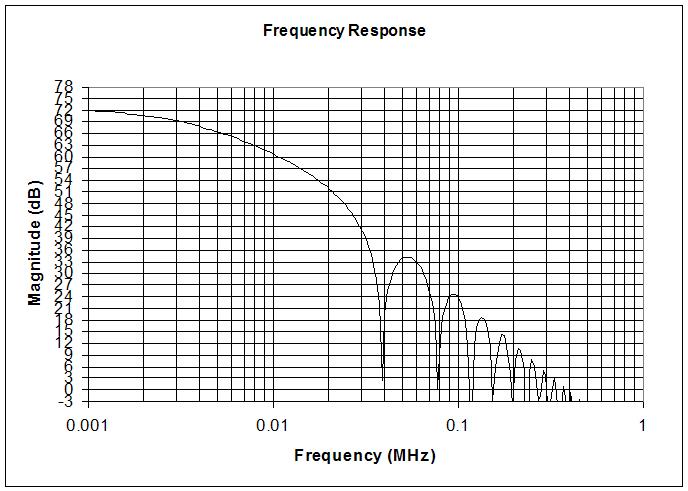
Playing around with a first order CIC by itself:

The above response uses a decimation of 256 (160MHz/256=625kHz output sample rate) and a comb delay of 256.  This gives a -3dB point of just above 1kHz, and alias suppression of roughly 50dB (reading the graph at 1/2 the output sample rate and subtracting this from the response at DC).  Data I/O widths are 16/32.  The comb delay could be formed from a single 8kbit BRAM (8192/32=256).  Output bit growth is 16 bits, which I believe 1/2 could be truncated (LSBs) giving a 24 bit input into the next stage.  More decimation would be nice as this would give the Hive thread running at 20MHz more instruction time between interrupts, though even 625kHz gives 32 instructions per sample - a 625kHz interrupt would also allow placement of the comb delay in software where it would be more flexible but would eat up main memory. 

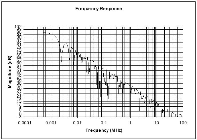
The use of 2 BRAMs of comb delay would give roughly 60dB of alias suppression and a decimated sample rate of 1.25MHz.  It's hard to know what will be enough here without testing in hardware, but it seems the ear can tolerate a certain amount of low level FM without noticing it.  I wonder what the physiological threshold is?

You must be logged in to post a reply. Please log in or register for a new account.