Let's Design and Build a (mostly) Digital Theremin!

Posted: 10/2/2014 9:40:01 PM
FredM

From: Eastleigh, Hampshire, U.K. ................................... Fred Mundell. ................................... Electronics Engineer. (Primarily Analogue) .. CV Synths 1974-1980 .. Theremin developer 2007 to present .. soon to be Developing / Trading as WaveCrafter.com . ...................................

Joined: 12/7/2007

Hi Dewster,

Mostly lost - ;-) ... but..

"This gives a -3dB point of just above 1kHz, and alias suppression of roughly 50dB"

This is the top level, as in, the worst case latency from the above would be < 1ms ? If I am understanding this right, that would be extremely good.

The following stuff I understand as being faster post-processing,

Possibly completely lost..

"The use of 2 BRAMs of comb delay would give roughly 60dB of alias suppression and a decimated sample rate of 1.25MHz.  It's hard to know what will be enough here without testing in hardware, but it seems the ear can tolerate a certain amount of low level FM without noticing it.  I wonder what the physiological threshold is?"

I am assuming this is all derivation of the pitch value - that the FM would be some cyclic numeric 'modulation' imposed on this value.. and here I am lost - What frequency would this modulation be?

Hey - I am probably not going to understand the answer anyway, and even if I did, probably wont have the slightest chance of making any useful comment, so please dont sweat to give an answer ;-)

Mostly I just popped onto this thread to say hi, because it can get lonely having no replies / comments..

Fred.


Do you realize you are getting close to 100 pages? Is this going to be a TW record I wonder? - some sort of award ceremony should be planned!


Posted: 10/3/2014 3:32:23 AM
dewster

From: Northern NJ, USA

Joined: 2/17/2012

"This is the top level, as in, the worst case latency from the above would be < 1ms ?"  - FredM

Yes, were this the only filter with an F3 this low in the chain.  In the pipeline before this filter I plan to have a simple naturally variable cutoff filter that lowers it even more for the far field.

"I am assuming this is all derivation of the pitch value - that the FM would be some cyclic numeric 'modulation' imposed on this value.. and here I am lost - What frequency would this modulation be?"

Pitch value, yes, sorry that I'm not being very descriptive lately (TMI: buried alive under a avalanche of volunteer work).  Being aliasing the FM frequency & amplitude are difficult to pin down.  The period measurer kicks out values at ~100kHz to 3MHz - it measures rise-to-rise and fall-to-fall of a ~square wave - which obviously also has harmonics with significant energy.

Any time one desires to lower the sampling frequency one must ensure there isn't significant energy above Nyquist, otherwise it will alias down into the passband.  This is non-linear distortion and therefore can't be removed later via linear approaches like filtering so it pretty much has to be nipped in the bud.  Ideally you'd crush it with some kind of brick wall LPF pre-decimation (sub sampling) but even approximations to this are generally computationally expensive, so you look for economical solutions that are good enough.

But what here is good enough?  I did a quick web search for FM / phase noise sensitivity of the human ear but didn't find anything of interest.  Need to do some experimenting on myself.  The threshold is probably rather high otherwise people would be complaining about all the likely egregious offenders out there.

"Mostly I just popped onto this thread to say hi, because it can get lonely having no replies / comments.."

You're my brother in arms Fred!  I'm treating TW like a blog / technical diary which must seem weird to a lot of readers (all 2 of them including me).  Thanks for supporting my babble, and I do very much value your comments!  We seem to have caught the same disease.  

Posted: 10/3/2014 5:07:33 PM
FredM

From: Eastleigh, Hampshire, U.K. ................................... Fred Mundell. ................................... Electronics Engineer. (Primarily Analogue) .. CV Synths 1974-1980 .. Theremin developer 2007 to present .. soon to be Developing / Trading as WaveCrafter.com . ...................................

Joined: 12/7/2007

OT.

Thank you, Dewster - Its great to be reminded of that infection! - even if mostly all that's left are the scars.

Brought back old memories - of my first American friend, a pacifist / draft dodger who came to SA, he was a born-again Christian at the time (like me) and fellowshipped in our church.. Also became active with me in the Anti-Apartheid movement.

Sadly, some elder in the church persuaded him of his "Christian duty" so he went back to the USA - I went the other path and joined the banned communist party - we lost contact in the '70s.

All seems so damn pointless and futile now - the barbarism and apartheid continues - only now its not based on color so much, its based on wealth.. New bosses, but the desperately poor are still desperately poor, the miners are still being shot at, nothing has changed except the delusion that the people are "free".. Even though, unimaginably, most are ever worse off.

Perhaps candles aren't enough..

Fred.

Posted: 10/5/2014 11:41:05 AM
dewster

From: Northern NJ, USA

Joined: 2/17/2012

"Perhaps candles aren't enough.."  - FredM

In an interview on a DVD I was watching a while back, George A. Romero stated that one of his biggest disappointments was the failure of the counter cultural revolution.  "We thought we changed the world.  All of a sudden, it wasn’t any better, any different."  With birth & death ignorance springs eternal, so it's a constant uphill fight.  If we all lived long enough to know better and remained healthy enough to do something about it this intraspecies warfare would have ended long ago.

Posted: 10/5/2014 12:13:35 PM
dewster

From: Northern NJ, USA

Joined: 2/17/2012

Expanded the CIC spreadsheet to do cascaded (polyphase) CIC:

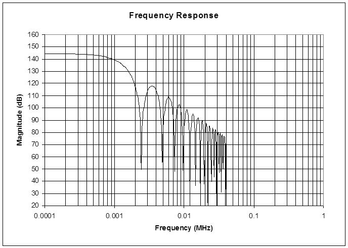
This is the previous CIC filter followed by a second CIC with 1/16 decimation and 16 comb delay.  As can be read from the graph, at Nyquist (~20kHz) the alias rejection is around 55dB.  Response at 1kHz is around -6dB due to the two droopy responses adding together (multiplying actually).

What's interesting is the second CIC operates at 1/256 of the system clock of 160MHz (polyphase!) so the decimation and comb delay have the same impact as the much longer first CIC.  The reason the alias rejection isn't vastly improved is because the increased attenuation slope is countered by the movement up that slope due to the lowered sampling frequency.

Using a simple first order LPF instead of the more complex second CIC I can get similar rejection / droop results.  With two first orders in cascade I get ~70dB rejection.  This LPF could likely be implemented with higher order and with more finesse in software and have better droop characteristics.  I'm toying with having a 32 instruction (=clock) loop running in one of the cores (rather than using the interrupt mechanism) to snag the data and operate on it (i.e. to do higher order secondary filtering down to ~1kHz BW).  Maybe I'm being overly cautious keeping the frequency number update in ultrasonic territory, but I don't want to take chances with sticky pitch and the like.

I can't say I've ever seen a CIC used exactly this way, i.e. a huge comb delay to give an extended 1st order roll off amongst the field of zeros.  Normally the comb delay is set to 1 or 2, and the response at the first hump is used as the attenuation, with higher orders used produce faster drop off.  But higher orders can easily lead to huge bit width growth, and here would require more FPGA hardware.  If you have a spare BRAM, the first order CIC with huge comb delay is fairly inexpensive hardware-wise, and (with decimation=256 and comb delay=256) the bit growth is 16, for an output of 32 bits for 16 in, which is right at the limit of the processor (though 8 bits could probably be discarded as noise).

Spreadsheet is here:

http://www.mediafire.com/download/l3a0a5lwl2iue09/CIC_combo_2014-10-05.xls

Posted: 10/6/2014 9:45:33 PM
dewster

From: Northern NJ, USA

Joined: 2/17/2012

Did some FM experiments on myself just now using the "Generate | Tones..." feature in Adobe Audition 3.0.  Tried sine, square, triangle, sawtooth.  A sawtooth around 1kHz seemed most sensitive to FM to my ears.  For the modulation frequency, values in the 10Hz to 20Hz range were the most audible, though I tried significantly above and below this as well.  Tried ramping the modulation frequency from 10Hz to 40Hz but steady state on / off comparisons seemed to reveal more.  Finally, I tried varying the modulation depth (entered as Hz in the dialog) and found 1Hz to be at or below the edge of my audibility.  So:

  20 * log10( 1Hz / 1000Hz ) = -60dB

This seems to be the maximum corruption level (of noise, aliasing, etc.) to aim for when it comes to processing pitch values in any domain (including analog).

Posted: 10/8/2014 1:39:07 PM
FredM

From: Eastleigh, Hampshire, U.K. ................................... Fred Mundell. ................................... Electronics Engineer. (Primarily Analogue) .. CV Synths 1974-1980 .. Theremin developer 2007 to present .. soon to be Developing / Trading as WaveCrafter.com . ...................................

Joined: 12/7/2007

Thanks Dewster - Useful information!

I haven't really used Audition's "generate tones" - but its a real useful tool.. I realized that I could generate sweeps using Audition which I can then import into Proteus as .wav's ... Now that is going to save me a lot of simulation time!

... Rather than having to build a VCO with wave-shaper (actually, I do this kind of thing so often I have created a VCO component I just drop in) I can simply place a generator and assign it to the .wav so the simulator doesnt have the overhead of simulating the VCO..

I can also take the simulation output to a .wav and thereby use auditions analysis tools, and also partition the design into  audio sub-sections which can work with the preceding stages audio output..

Real useful at this stage, as the design gets huge and full simulations take hours - I can generate approximately the right input waveforms, quickly test the next stage and hear / analyze the results, take that output to the next stage etc.. Then when I have what I think I want, can go back to the first stage and actually run the heterodyning etc, save and check the audio output, and feed this into the following stages.

Because my HF oscillators are both capacitive and voltage controlled, I can actually set up a CV sequence to "play" the instrument - Partitioning the design in this way, I am hoping to actually be able to generate a "performance".. I have tried this before with the full system, but after running all night I come back and the system has crashed (and often only got 10 seconds into the simulation before crashing)..

Being able to actually hear the instrument playing before its built would be really encouraging and interesting (I am actually videoing my attempts, so that if I get this right, I can YT it.. ) but I must also be careful not to let this become a "project" in its own right - Its of absolutely no practical use to anyone ;-)

Fred.

One interesting hypothetical question..

If I have a simulation of analogue oscillators and analogue heterodyning with analogue audio processors following it.... What is the result in terms of the great analogue / digital "contest" ?

I think the result must technically be "digital" because all components simulated are done so numerically with finite resolution.. But depending on how one sets the simulation up (what tolerances one allows for currents and voltages, and what time-steps / resolution one sets for convergence etc) and how long one is willing to wait for the simulation to complete (the higher the resolution, the longer it takes) one can certainly get way better than in needed for the audio output resolution..

Because this is a long way from real-time (1 minutes of audio can easily take an hour to simulate at high resolution on my system - hopefully partitioning will speed this up) I think that for practical purposes the audio output will be "analogue"... Which must (if true) mean that an "analogue" instrument could be produced with high enough resolution / fast enough real-time digital circuitry.

There are "analogue emulation" synthesisers available, both as hardware and soft-synths.. Some are damn good - but as yet, I have not heard ant that were absolutely convincing (perhaps they are under a 64 bit OS on a fast quad core - I am still on 32 bit XP with moderate speed dual core, so probably way below the minimum needed)

Posted: 10/8/2014 3:12:16 PM
dewster

From: Northern NJ, USA

Joined: 2/17/2012

"I haven't really used Audition's "generate tones" - but its a real useful tool."  - FredM

CoolEdit was a marvel of shareware, and Adobe actually improved it substantially with 3.0, though the price jumped crazily.  Then everything went down the crapper with the subsequent complete rewrite / gutting, and at this point (with the additional sins of PDF and Flash foisted upon us) I wish I had a time machine in order to go back and kill Adobe's great great grandparents.

"If I have a simulation of analogue oscillators and analogue heterodyning with analogue audio processors following it.... What is the result in terms of the great analogue / digital "contest" ?  <*snip*> There are "analogue emulation" synthesisers available, both as hardware and soft-synths.. Some are damn good - but as yet, I have not heard ant that were absolutely convincing"

The instant one records analog digitally and is satisfied with the result I think many arguments regarding digital processing go out the window as there are quite a few (albeit highly oversampled) digital filters in that chain along with the quantization of levels and sample timing.  Regarding digital generation, I suspect many analog simulations done with DSPs cut too many corners in terms of parameter update bandwidth, aliasing, and model complexity, and the results of this are audible.

Posted: 10/8/2014 5:39:27 PM
dewster

From: Northern NJ, USA

Joined: 2/17/2012

Coded up the CIC in SystemVerilog and put the finishing touches on it this morning.  By using full width math throughout the internal arithmetic can be made signed / unsigned agnostic, so handling either is simply a matter of sign or zero extending the input value.  With 16 bit input, 32 bit output, R=256, M=256, one 8kb BRAM, one accumulator, one subtractor, and one output register, it runs >200MHz and consumes 84 logic elements, all of which are almost perfectly utilized in terms of LUTs, carry chains, and registers.

Sampling this in the processor at 625kHz, there are 32 clocks to do further filtering.

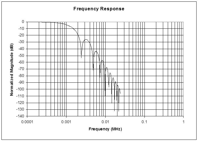
Above is the single CIC followed by a proposed droopy (Q=0.5?) 4th order IIR LPF in software.  Response is down ~4dB at 1kHz.  Sampling this in software at the audio rate (48kHz) gives almost 100dB alias rejection.  I think this will be entirely satisfactory, though of course experimentation will tell.

I should also mention aliasing a bit.  It isn't entirely unpredictable as the input is heterodyning with the Nyquist frequency, or 1/2 the sample rate - the input "folds back" into the passband at Nyquist.  So if aliasing is confined to the higher regions it can be reduced via subsequent LPF, particularly in an oversampled regime.  I guess my point is that aliasing need not be "stamped out" by the first decimating stage, only reduced to some reasonable level based on the combined influence of subsequent LP filtering.

Posted: 10/9/2014 1:10:52 AM
FredM

From: Eastleigh, Hampshire, U.K. ................................... Fred Mundell. ................................... Electronics Engineer. (Primarily Analogue) .. CV Synths 1974-1980 .. Theremin developer 2007 to present .. soon to be Developing / Trading as WaveCrafter.com . ...................................

Joined: 12/7/2007

A word of warning to anyone contemplating using PSoC 3,4 or 5 - Particularly if you are used to PSoC 1 PWM's..

I have just been badly burned..

Had everything working to a level that I could pin it out, and stick real oscillators on..

Had been using internal clock signals for testing...

WTF!

The damn TCPWM blocks on these F**King devices will only accept clocks derived from internal sources! (well actually, will only allow clocks from the master clock divider chain) - Unlike the PWMs in PSoC 1 where you could wire the clock input to a pin (and so implement frequency division on external inputs) you are strapped.

Ok - You can implement PWMs / Counters etc in the UDBs (PLD's) - But I have used every available UDB resource for other things which cannot be done in the fixed blocks - I have four 16bit TCPWM blocks unused, and the most elementary basic functions cannot be used in my application because I cant get signal to them!

I have raised a case with Cypress about this - Oh, its my fault - One line in the TCPWM data sheet does tell you - but PSoC Creator allows one to wire a pin to the PWM clock input (I tested this quite early just to be sure I could route things the way I wanted later) , and the fitter dumps an error message and stops compilation!

Been here before with Cypress. Why the F dont I ever learn from past mistakes!?

Fred.

Oh - Gordon.. You shouldn't need to worry - The PSoC 4 works perfectly for simple configurations.. Problems probably only appear if you try to use all its available resources and dont realize that the fixed blocks might be useless.

And if you havent bought a board yet - I may well have a few I will want to get rid off!

You must be logged in to post a reply. Please log in or register for a new account.