Let's Design and Build a (mostly) Digital Theremin!

Posted: 12/8/2016 3:43:22 PM
dewster

From: Northern NJ, USA

Joined: 2/17/2012

Hi 3.14 (pi?)

Thanks for prodding me re. github!  I've been meaning to look into getting these projects on something like that for like forever.  I've got Hive over on opencores.org, but the site is kinda cumbersome and kinda dead seeming as I get only maybe one doc download per day.  So I signed up for a free github account and will investgate the process shortly.  If you have any hints or tips I'm all ears.

Yes I calculated the coils via my spreadsheet.  I also measured them and adjusted them a bit after the winding and before the I installed the leads and nail polish, though final measurement and adjustment isn't really necessary for this application.  Larger diameter wire has lower DCR and less skin effect, and this helps keep Q high, though you're also dealing with radiation losses, so Q can only be so high in the completed circuit, and one quickly encounters diminishing returns.  I usually aim for a coil that has coil height:diameter ratio somewhere around 1:1 to 2:1.  1:1 will provide close to ideal inductance for a given overall wire length, higher ratios give more distance between the drive end and the sense end (likely less intrinsic capacitance) though nothing in this range of ratios is all that critical, and you generally want the coil height to be a minimum of maybe 30mm or 40mm just to keep the capacitance down.  I suppose I also try to not waste copper if it's not necessary to the function.  

I maintain PLL lock on both the pitch and volume sides.  I know what you're saying though, as analog Theremin volume sides often work as you describe, and one could conceivably build a digital Theremin that worked that way.  I think FredM's idea of "upside down" circuitry was similar to this, with one frequency driving both antennas.  But I've found that with sufficient frequency difference and sufficient distance separating the antennas, the interference is moot.  Indeed, no Theremin would work if this wasn't the case.  Phase lock gives you the highest amplitude voltage swing in all situations, and the highest selectivity and sensitivity.  Not using phase lock would also introduce a strong non-linearity in the response.

========

What kind of test equipment do you have?  You should have a decent scope, DMM, function generator, and LC meter.  I can give you suggestions as to brands and such if you like.  I have an old Tektronix TDS210, a Fluke 76, a Goldstar FG8002, and a cheap though very useful LC meter from eBay.  I also have an FC-1 frequency counter that has come in handy.  You can get inexpensive tiny capacitor value assortments from eBay.  You can use a standard plastic breadboard for experimenting (though you have to be aware of the parasitic capacitance).

If you have a scope and a function generator, and you want to get a good intuitive feel for what is going on with the LC side of things, I can show you a simple setup that I've used quite a bit.  With it you can clearly see the influence of your hand & body out past 1 meter, see the influence of mains hum, examine the relative stability of various oscillators, and quantify total Q (coil, antenna, drive, sense).

Posted: 12/9/2016 8:57:33 PM
3.14

From: Buenos Aires, Argentina

Joined: 9/14/2008

Hi dewster, yeah an imprecise version of pi here :)

Working with github has a learning curve. The idea is that you have a local repository (versioned) in a normal directory, and pull from/push to the central repository at github. This requires a command line tool or a gui provided by github. The good thing is that everything is versiones, you can delete stuff and it stays in the history. You can start by putting al your stuff in a directory and order things. In your case I would just put latest versions of things. A possible subfolder arrangement could be


simulation, research and design

   analog

   digital

   inductors

product

   schematics (the analog front end, wiring to fpga) 

   pcbs

   verilog

   construction (i.e. for inductor sketches)

   docs


The product folders will always have latest stuff as it evolves. You can just setup this in your local machine, then run "git init" and then create the repository at github and follow instructions to push. I can also create it myself in my account with the files at mediafire and transfer the ownership to you.

====

I think I will start grabbing components and stuff soon. 

The hard part is equipment, currently I only have a (not very good) multimeter. As this is just a hobby, having a big oscilloscope (a tube one) has no space, and a small LCD one has no budget :) . I was speculating with USB oscilloscopes but I won't plug it to the the Mac, so probably I should throw away old stuff to make space and/or get budget.

I studied electronics at high school but then turned to computer science, where I've been the last 30 years. So having a lab is like going back to school :) My first come back was like 6 years ago when I built the EW.  I wanted do it "the right way" so I did the schematics, simulations, pcb design based on the schematic's "net", etc. And I enjoyed the "model to thing" engineering approach. Without instruments it was hard to make it work, and this held me back from building other electronics projects I had in mind. So maybe it's time to have a lab!

So my first goals are:

1) Setup a useful lab that I can afford. I do accept recommendations. I know Tektronix, HP, Agilent, Fluke are excellent, but probably I should consider other "second line" brands. Also some DIY freq generator ?

2) Get the FPGA board(s). I would prefer to buy two cyclone II instead of only one cyclone IV, except if you tell me it's wasted money.

3) Learn verilog. I'm currently starting to play with Icarus Verilog, which has a simulator and can display things with GTKwave. Copied/pasted examples and simple tutorials seem to work, so I would start serious stuff. I wonder how do you simulate/test "in paper" the whole theremin?, I mean sweep antena capacitance and simulate the NCO. I guess I need to write a a test in verilog which emulates the AFE... but probably there is another shorter path?

4) Read something about DSP?

5) Setup the Quartus environment (for which I also need a virtual machine as I use Mac)

6) Play with real LC and learn all that...

For my next theremin I think the "overall" design would be: FPGA/DewsTeremin based, capacitance sensing (decoupled from generation), digital signal generation to SPDIF (leave for later a separate "internal" SPDIF+DAC+Amplifier module). On the other hand, I'd like it to look and feel "classic" in all aspects: the antenna shapes, the enclosure, the controls, the voice...


Posted: 12/10/2016 12:43:51 AM
dewster

From: Northern NJ, USA

Joined: 2/17/2012

Hi 3.14,

Thanks for the github explanation!  I'll get on it soon, and when I do I'm sure I'll have questions.  Am currently revisiting the Hive UART for what feels like 1000th time (but now it's better than ever!).

=====

1. You don't need the best DMM in the world (though it never hurts).  You might look at EEVBlog for suggestions.  I've been trying to convince myself I need a new scope, and keep drooling over the Rigol DS104Z ($400USD).  You need a half way decent scope for this kind of work.

2. Cyclone 2 is old and I personally would avoid it.  I've got a Cyclone 3 board laying around that I'll probably never use now that I have a Cyclone 4 board (more block memory).  If you're putting a processor in there you can use Hive, though an external processor might make more sense for most people as it would be more easily programmed at a higher level and you could do stuff like reverb.  Why don't you wait until you really know what is going in the FPGA(s) before you buy?

3. The simulator in Quartus 9.1sp2 (sadly, the last version to have it) is pretty nice, and you can get experience with the Altera toolset at the same time.  In the project settings you can select "timing" or "functional" sim, I usually do "functional" because compile and sim are a lot faster.  SV (SystemVerilog) is definitely the language you want to use IMO, I started with VHDL and it's really overly verbose.

There isn't a need to simulate the entire Theremin, just the unknown pieces.  I've done enough C measurements and sims so that I pretty much know what's going on in a quantified way.  I've done LC sims in Excel, and I heavily simulate all of my SV code.  I observe the hardware results on my scope, and analyze sound generation via Adobe Audition.

I assume you haven't done much concurrent digital design work?  That's the hard part IMO.  I've looked around, but there really aren't any good books on the subject.  We all seem to learn by looking at other people's code and mucking around.  I use a system of block diagramming and wave sketching that gets me through even the biggest projects, but I've never seen anyone else do this.  I've found that I can't even do the simplest bit of coding without at least diagramming it.

4. Get a copy of "Musical Applications of Microprocessors" by Chamberlin.  It's old (~30 years) but it's a great intro.

5. There are Linux (red hat) versions of Quartus too.

6. Once you have a scope and a function generator I'll show you some really simple experiments.

Re. the "classic" look and feel in all aspects:  For a digital Theremin, a plate antenna is really the way to go.  Slightly more linear and much more sensitive than a rod antenna.  I don't really care what it looks like, and my pitch antenna plate should be playable by anyone who is comfortable with and has developed playing techniques for the standard rod antenna.  Form follows function, baby. ;-).  Tradition is much too strong in this field.

Posted: 12/14/2016 11:35:45 PM
dewster

From: Northern NJ, USA

Joined: 2/17/2012

Processor Memory Access Width

Processors often support byte read and byte write in hardware.  The byte read can be easily replaced with software reading 16, 32, 64, etc. bits, and a subsequent shift or two isolates the desired byte.  Doing this with byte writes is more problematic because the write requires a read, a replacement of one byte, then a write, which is not atomic.  That is, another thread could write the same location in the middle of this process and really mess with things.  One solution is to somehow avoid writes by other threads always, or at least when a given thread is doing a software byte write.

Hardware byte read is fairly trivial if you've got cycles in the ALU pipeline to shift and isolate the desired byte.  But there are other downsides of supporting byte read and write in hardware: 1. the LSbs of the address may become externally rather moot for wider accesses;  2. which can reduce the effective address space by half or more for a given address width; 2. wider data accesses become more sensitive to design questions of byte alignment - can you read 16 bit data starting at both even and odd byte addresses, or only at even addresses?  For 32 bit accesses there are four possibilities, for 64 bit accesses there are 8, etc. and machines that sidestep the alignment issue must then contend with inefficient storage of values, particularly in a Von Neumann machine where values and opcodes are stored in the same memory.

I don't think I ever specifically decided to not support hardware byte access in Hive.  It's probably more the case that I saw it as difficult and not very necessary, and so just didn't.  Eight bits just can't do that much either as data or opcode.  16 bits are very useful as opcodes, but not so useful as data.  32 bits can do a heck of a lot, and can support reasonably ranged packed floats (single precision) as well, but are probably overkill for opcode use.  It would be nice if we could pick a single width for the data and opcodes, but alas this generally isn't the best from an efficiency standpoint.  A 16 bit opcode and a 32 bit register width seems to be the sweet spot for a modern smaller processor.  

Since the Hive opcode width is 16, memory read and write at this width has been supported from day one, and indeed 16 bits is the fundamental data unit in Hive because an address is the location of a 16 bit value.  32 bit access (both aligned and unaligned) was added once I recognized the value of reading and writing entire 32 bit register values.  So there are 8 bit signed literals, 16 bit signed and unsigned literals, 32 bit literals, unsigned 16 bit memory reads and writes, 32 bit memory reads and writes, as well as 32 bit register copy/move, and 16 bit signed and unsigned register copy/move.

Now that I'm doing a lot of work with ASCII data, which operates on the byte level, I've decided to add a couple of opcodes that facilitate the isolation of byte values.  It's easy to do this already via left and right 24 bit shifts, but there are two slots open in the logical section of the ALU, so it's something of a natural.  So the new ops are register copy/move byte unsigned and signed (CPY_BU and CPY_BS) and give the the option of copying/moving the result to another register at the same time (immediate shifts don't allow for a simultaneous move).  Moves in a two operand machine are always welcome, and probably even more welcome in a register / stack hybrid like Hive.

I've done this, and the FPGA LE (logic element) count has gone from ~2500 to ~2600.  The speed seems perhaps a tad slower at ~195MHz, but it's hard to really know without doing a lot of seed sweep builds with the before and after, and even then you have to have the "right" seeds in your sweep.  I've already decided that I'm not going to run Hive above 185MHz or so, just to keep build times reasonable, so not hitting 200MHz after a short seed sweep isn't breaking my heart like it used to.

I updated the simulator and assembly compiler to reflect these hardware changes.  While I was in there I decided to add a view into the UART TX FIFO buffer, which is working pretty well.  I also streamlined / refactored some of the HAL assembly code interpretation code.  

And, of course, while I was mucking around in the Hive SV code I just had to redo the UART for the millionth time.  I separated the TX and RX registers, removed the error and loopback bits, and inverted the ready bit sense.  This makes it trivial to read and write bytes from and to the UART sections without any byte filtering.  I modified the UART code itself to have both master and slave ports - master for direct connection to a FIFO, slave for direct connection to a register set.  This arrangement works out surprisingly well.  UARTs seem simple but they bring up a lot of issues surrounding access buffering, handshakes, and division of labor in the SW driver.

Posted: 12/20/2016 11:21:10 PM
dewster

From: Northern NJ, USA

Joined: 2/17/2012

Handshakes (no, not the DT's ;-)

When designing digital circuits you often need to route data from one blob of logic to another.  If the data doesn't change on every system clock then you need some way to signal newness.  This could be as simple as an active high enable from the data source. Sometimes the data sink can't take data on every clock, so it sends some kind of "ready" signal upstream to the source.  These are handshaking scenarios, and there are many ways to approach and implement them.  You want to use simple, robust, self-correcting handshakes that avoid issues such as deadlock, livelock, etc.

For a practical example let's look at UART interfaces.  The TX UART takes a parallel byte and transmits it serially. It takes quite a few system clocks to transmit the byte over the relatively slow serial connection, so the TX UART must tell the parallel interface when it can and can't accept data.  It can do this in one of two ways, either as a bus master or bus slave.  As a bus slave, the TX UART tells the bus master when it can accept new data, and the bus master tells the slave when it has written it.  As a bus master, the TX UART looks to see when there is new data presented by the bus slave, and tells the slave when it has read it.  So the master controls ready, and the slave controls the read/write strobe.  Processor register buses tend to be masters, so it seems natural to design the TX UART interface to be a slave.  But what if we want to put a FIFO buffer between the processor register and the TX UART?  Both sides of the FIFO are slaves, which is fine for the processor bus side where we would have master & slave, but the connection between the read side of the FIFO and the TX UART would be slave / slave.  This won't work without some extra logic or similar.

One approach is to add the additional logic as a simple interposing shim of sorts, which either turns one of the slaves into a master, or acts as a double master.  Another is to provide both master and slave handshake ports on the TX UART component, and only use the one you need given the presence or absence of the FIFO (it's nice to have this kind of thing configurable at build time).  I've messed with FIFOs and UARTs so much that I can safely say I've likely tried ALL approaches, and neither of these is ideal.

When a UART doesn't have a FIFO attached as a deep source of data (or deep data sink in the case of a RX UART) it is often double buffered, which means there is an extra layer of buffering at the parallel interface.  So if a processor wants to transmit two bytes over the TX UART it writes the first, and then only has to wait a short time until the UART sticks the first byte in the serializing shift register before writing the second byte.  Double buffering is even more important on the RX side because it allows the previously received data byte to just sit there waiting on the processor to read it while another incoming byte is being being parallelized.

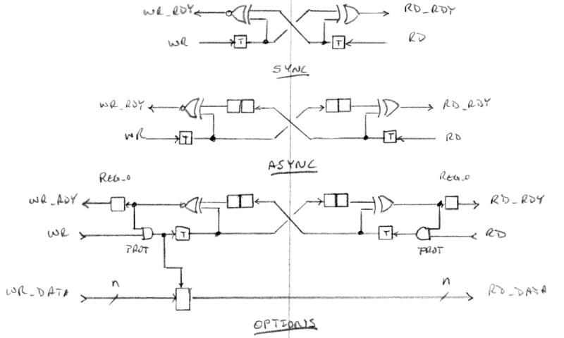
We can build double buffering into our UARTs, but it does complicate things some.  In particular, an RX UART with double buffering, master handshake, and slave handshake can get pretty hairy - this is right at the edge of complexity that I feel comfortable managing in a single component.  Is there a way to simplify things?  Yes, and the secret is to make the double buffering buffer a separate one deep FIFO.  Pulling this buffer out of the UART and designing the UART handshake to be master only significantly simplifies the UART logic, and this arrangement also allows us to easily swap in and out a real FIFO if desired in place of the one deep FIFO.  We can draw on FIFO design concepts in order to construct the buffer:

At top is the basic idea for the synchronous (one clock domain) slave / slave handshake mechanism.  In the quiescent state output wr_rdy is high and output rd_rdy is low.  Since write sees ready it can pulse input wr, which toggles the flop and causes wr_rdy to go low and rd_rdy to go high.  Read sees this ready so it can pulse input rd, which puts the outputs back in the quiescent state (but with opposite toggle flop output states!).  This is a super simplified version of the conventional FIFO cross pointer operation because the pointers only have two states.

In the middle we see an asynchronous version (i.e. separate write and read clocks) where the state from the other clock domain is sampled twice in the local clock domain to eliminate metastability issues (violating setup / hold at the input of a clocked flop can cause the flop output state to change much more slowly than anticipated, but two flops in a row sufficiently restores snappiness).  Note that the local state feedback is immediate, and all latency to/from the other side won't cause errors as long as the handshake protocol is observed individually by both sides locally.

At the bottom we see the asynchronous version with pointer protection (the AND gates prevent not ready reads / writes), ready output registering (to increase the top speed of the logic), and the registering (latching or updating and holding) of the parallel data with a valid write.

The TX UART logic is now really trivial, and the RX UART logic finally feels mentally manageable.  I also used this single level FIFO at the input of the LCD component, which makes FIFO buffering there optional.

Finally, I added an asynchronous version of the buffer to the register interface of the SPDIF TX component - this provides data storage and a new readable ready feedback signal to the register set, so the SPDIF software can either poll the register or rely on the PCM interrupt to service the SPDIF hardware.  (The register set and the SPDIF component are in two different clock domains, which complicates data transfer and handshaking.)

Posted: 12/25/2016 4:56:30 AM
dewster

From: Northern NJ, USA

Joined: 2/17/2012

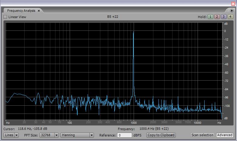
Got the handshake working at the SPDIF register set interface, wrote a quick 1kHz sine wave generator in Hive assembly:

lbl[0] s0 := 0                 // sin init - THREAD 0 BEGIN
       s1 := 0x8000            // cos init (amplitude)
       s2 := 0x21800000        // alpha (frequency)
lbl[1] s3 := reg[0x8]          // <loop start> read SPDIF L
       (P3 < 0) ? pc := lbl[1] // loop if busy
       reg[0x8] := s0          // sin to SPDIF L
       s0 *s= s2               // sin * alpha 
       P1 -= P0                // cos -= sin * alpha
       s1 *s= s2               // cos * alpha
       P0 += P1                // sin += cos * alpha
       pc := lbl[1]            // <loop end>

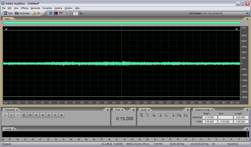
and looked at the results in Adobe Audition:

Super clean!  Full 16 bit resolution, even going in through the analog input of my motherboard audio jack.  

Now to make a software low pass filter and run the pitch operating point through this gauntlet to examine the noise spectra there.

Posted: 12/26/2016 5:47:44 PM
dewster

From: Northern NJ, USA

Joined: 2/17/2012

Characterizing Noise At The "Antennas"

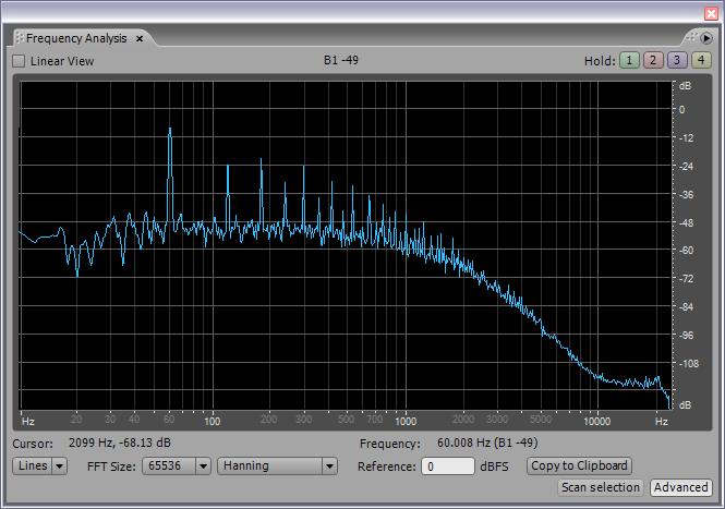
I wrote a simple routine in Hive assembly which snags the pitch antenna number at the PCM rate via the SPDIF 48kHz interrupt, first order high pass filters it (-3dB @ 7.5Hz), attenuates it by a factor of 4 (to prevent overload at my SPDIF to analog box which only has a 16 bit analog range), and writes the result to the SPDIF TX component.  I then captured the result as audio via Audition:

Above you can see what the antenna picks up in terms of environmental noise.  This is an AC signal riding on top of the DC pitch number.  Not surprisingly, the vast majority of the noise is 60Hz mains hum and harmonics of that.  You can also see the action of the anti-aliasing filter, which has cutoff of ~1kHz and is 4th order, which gives ~24dB / octave slope (most easily read from the 4kHz to 8kHz interval).

Analyzing the amplitudes, the 8th harmonic is 24dB below the first, so they are falling off at ~8dB per octave.  The 1st harmonic is ~40dB above the noise floor, so killing it is job one.  The problem with using a comb filter to do this is they only work on odd harmonics, so you can kill the 1st, 3rd, 5th, etc. (@60Hz, 180Hz, 300Hz, etc.) with a comb at 60Hz, but you need a second at 120Hz to kill the 2nd, 6th, 10th, leaving the first "hole" uncovered at the 4th harmonic, which you need a third comb at, etc.  The question then is how many combs to use, and where to put a really steep low pass filter to kill the rest.  If we could kill them all we might improve the pitch number by 40dB, or 7 bits of precision, which is quite significant, and killing them would prevent AM & FM intermodulation of the Theremin audio output too.

Comb filters memory use is directly related to the frequency of the first notch.  A 60Hz comb filter requires 400 32-bit memory locations reserved.  A 120Hz comb filter only requires 200 slots, and a 240Hz filter 100 slots.  So no matter how many combs are implemented a maximum of 800 locations are needed (per antenna).  For 50Hz mains hum the maximum memory slot use would obviously increase to 800 * 60 / 50 = 960.

=============

I just wrote another routine that kicks out the pitch number as hex to the UART every second or so.  My hand next to my shoulder reads around 0x6CAD00000, my open hand a couple of inches away from the center of the pitch antenna reads around x67000000. This is a difference of 0x5AD0000 or about 100,000,000 decimal.  But these aren't nice round numbers, there is quite a bit of noise. The bottom four hex digits are bobbling around, and the fifth most significant is bobbling by one or two values.  So of the 0x5AD0000 we can only trust the 0x5AD part or so, which is 12 bits of information.  Double checking this with the high pass filtered value, there is a peak to peak amplitude variation of 50k, and this is attenuated 4x to prevent clipping, so there is 50k * 4 = 200k. This is approximately 18 bits of noise, or 4.5 hex digits, exactly what we can see by eye via the UART hex data.  12 bits of info is just barely enough, so we definitely need to address the noise issue.

I'm not sure why the noise isn't simply 60Hz sinusoidal?  Why the strong harmonics?  It could be that the antenna is picking up clipped 60Hz from the variety of electronic devices in the environment that rely on rectification of the power line voltage.

If anyone wants to "hear" what the antenna "hears" I posted a 4 second MP3 here.

[EDIT] Oops, I think my HPF was incorrect and messing with the waveform.  Picture and MP3 above have been updated.  60Hz is ~12dB stronger than the other harmonics, and the MP3 sounds more like the hum you hear when touching a microphone input and such.

Posted: 12/27/2016 5:34:49 PM
dewster

From: Northern NJ, USA

Joined: 2/17/2012

Crush, Kill, Destroy

Routing the operating point to SPDIF is incredibly revealing.  I found several glitchy points in the pitch field that I hadn't previously detected via watching the scope alone. :-(

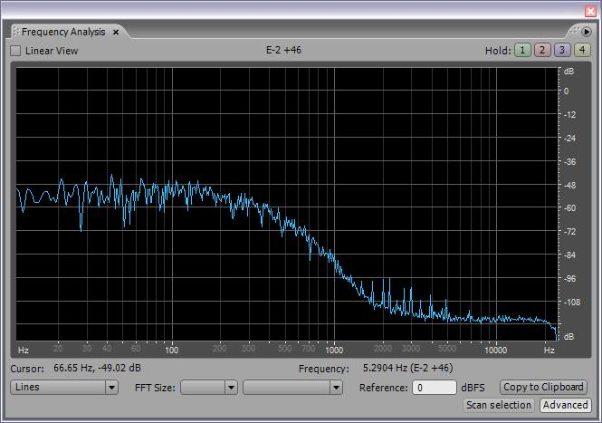
Here are the results of running the operating point through four comb filters (freqs = 60, 120, 240, 480Hz; attenuation Q = 2^-4), a 1st order high pass filter (freq ~7.5Hz), and a 4th order low pass filter (freq ~ 240Hz):

All the mains hum spikes are crushed, and peak-to-peak noise is down from 50k to 6k.  No clue how playable this is, have to somehow address the sticky points first.

What's interesting is that the noise floor above isn't constant, but varies quite a bit depending on where my hand is.  I think the NCO needs more dither.  

[EDIT] Here's what I'm seeing in terms of sticky points, I recorded my hand slowly approaching the antenna then slowly withdrawing:

If you squint you can see the symmetry of the sticky points on either side of the cursor at center.  They don't look so bad here because they are largely 4th order high pass filtered out (to reduce the influence of the movement of my hand).

Posted: 12/28/2016 10:09:39 PM
dewster

From: Northern NJ, USA

Joined: 2/17/2012

Ask Me About Dither

Tons of progress since yesterday.  I upped the dither noise amplitude quite a bit and all of the sticky points disappeared.  Up to a certain point, increasing the noise doesn't really increase the noise floor, which might seem counter-intuitive.  What's happening is the noise whitens things up, which causes the peaks flatten out into the noise floor, and this only raises the floor a bit.

Here is my hand going from my shoulder to maybe 1" from the pitch plate, and then back:

Up until today I never felt like I had a firm grip on the subject, but can now state that I totally understand what is going on regarding dither in a digital LC PLL.  

The key is this: the dither noise at the FPGA output pin driving the input of the LC tank must sufficiently "shake things up" at the output of the LC tank so that the FPGA input pins see in excess of 1 clock period of dither.  The LC tank Q acts like a phase noise filter, so the amplitude of the driving noise has to be considerably larger than 1 clock period in magnitude.  And for a given LC with a given Q the optimal amplitude will be a constant (which simplifies the design of the dithered NCO).  Any "sticky points" are purely an input sampling phenomena.  That's it.

Today I increased the input sampling timing precision by using an FPGA DDR element at the PLL input pins.  With the core clock at 180MHz, this gives an effective input sampling rate of 360MHz (or 2.8ns).  The required dither amplitude dropped by a factor of 2, and the noise floor seems to be a bit lower because of this.  I want to play around with noise shaping of the dither to see if I can reduce it even more.

Posted: 12/28/2016 10:43:44 PM
3.14

From: Buenos Aires, Argentina

Joined: 9/14/2008

I appreciate very much your work. I read your posts in waiting for the scope (Hopefully a Ds1054Z) to start my own fun :)


You must be logged in to post a reply. Please log in or register for a new account.