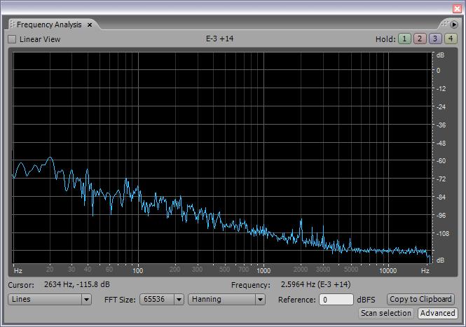
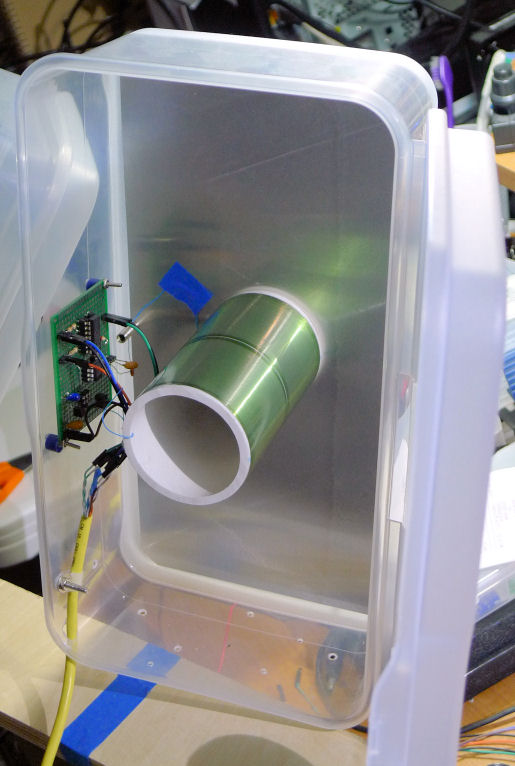
"The trick is to digitally acquire this without significant degradation." (-- moi)
Major milestone passed (like a kidney stone, LOL) yesterday. I've been working on the LC DPLL SystemVerilog code, adding input parameters, auto calculating others (some that influence the hardware synthesis, others just for informational purposes), altering the clocking arrangement, and radically changing the way the pitch and volume operating points are obtained and processed.
I suppose parameters are a form of premature optimization, but when you have a filter-like structure such as a DPLL you don't want to have to stop and think for 10 minutes every time you change an accumulator width or a bit shift distance. When you're experimenting it makes sense to implement the "knobs" you want to adjust as build parameters. Otherwise, operator errors tend to get incorrectly chalked up as failed experiments.
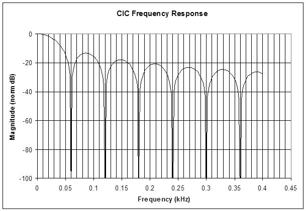
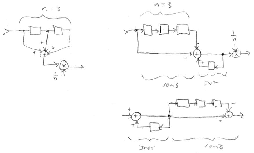
Anyway, the main breakthrough here is the implementation of a second order distributed CIC filter to get the pitch and volume numbers into the software domain of the processor. There is an NCO in the DPLL, and if you think about it, what is going on is the accumulation of an input phase increment. The larger the increment the higher the frequency of the NCO output. What we want in software is a band limited version of the frequency increment, and I was doing this with a 4th order low pass filter in hardware. What I'm doing now instead is to take the accumulator of the NCO and feed it to a second accumulator, and this combination forms a second order cascade of integrators. The output of this is sampled at 48kHz and passed to the processor via an interrupt. The software runs the sample through a second order cascade of differentiators - and voila! - out pops the NCO phase increment! So the NCO is an integral part of a second order CIC, where half of the CIC is in software where it is exceedingly trivial and essentially free, and as a result I was able to remove a ton of FPGA logic. (Hardware reduction isn't a high priority for this project, but it never hurts, because the more stuff you shovel into an FPGA the longer it takes to build, and the more difficult it becomes to meet timing closure.)
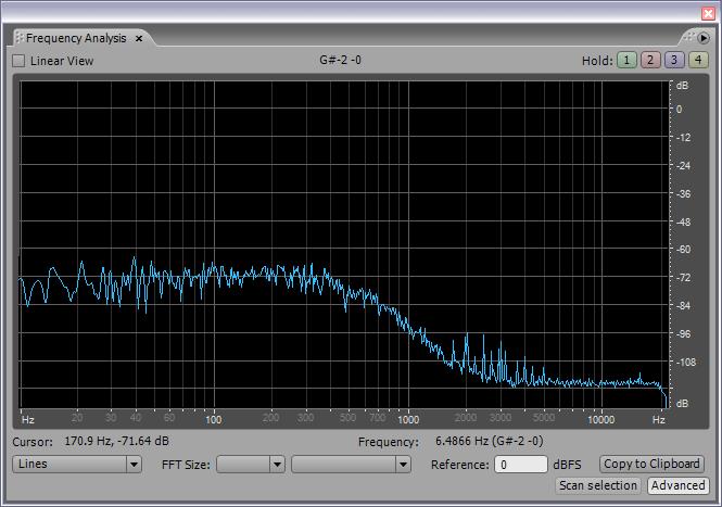
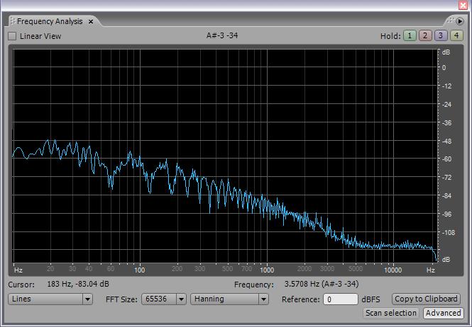
It was difficult getting all of this working, so I started with the first order CIC (just feeding the NCO accumulator - sampled at 48kHz - to the processor, and a single differentiating stage in software). Once I got that running and felt comfortable with it, I tackled the second order case. Here is what I'm now seeing in terms of spectra of the pitch operating point:
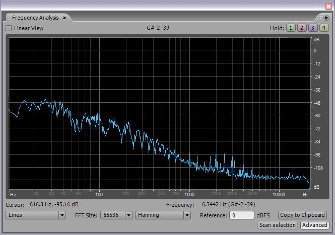
I'm doing a bit shift of 5 after the HW/SW CIC before feeding it to the mains hum CIC, then a 4th order LPF, and finally a 4th order HPF for the SPDIF output. The software is also kicking the operating point out the UART connection, and I'm seeing six or more hex digits of really clean data there.
To get the HW/SW CIC decimation (down sampling from 180MHz to 48kHz) to work right I had to alter the clocking to keep the decimation factor constant. So the DPLLs and the SPDIF would ideally both be clocked by 48kHz * 128 * 32 = 196.608MHz, but the closest I can get with an FPGA clock tree PLL is 50MHz * 59 / 15 = 196.667MHz, which is +298ppm off the exact number, but I believe this is OK for SPDIF. It's about +1/2 a musical cent, which should be undetectable by human ears in terms of musical pitch deviation. I had to work on the SPDIF component to get the speed up and to include a clock pre-scaler, but all of this has worked out rather well because the processor core clock is now largely independent of the Theremin logic clock. Down the road I could perhaps get the processor core clock up to 197MHz, at at that point I could cascade the two PLLs and get much closer to the ideal SPDIF clock rate.
Not seeing any sticky points, but there is a significant level of dither being applied to the LC tank. The dither gets filtered by the LC, and this actually may be a problem, because the LC DPLL compares the input LC drive to the LC output and, since the input dither is quite a bit higher than the output dither, the difference is probably injecting large levels of noise into the downstream process. I believe this large difference is also directionally incorrect in terms of phase error. I will try independently dithering the reference and the tank (same noise but at different levels) to see if this helps to lower the operating point noise floor. If it does, I may rewire the antenna drive boards to accommodate it (to keep the reference and quadrature analog delays the same).
This distributed HW/SW CIC filter integrated into the NCO is quite straightforward, economical, and very elegant - it's possibly one of my most fundamental contribution towards the realization of the modern digital Theremin, basically a stripped-down version of what's going on with the delayed sweep scope (though the scope scenario skirts aliasing by always triggering at the same point on the input wave). It would be interesting to integrate the hum CIC filter into this too, but that would require excessively wide operations, and having the hum filter in software really isn't a big deal.
