Let's Design and Build a (mostly) Digital Theremin!

Posted: 2/8/2017 7:28:51 PM
dewster

From: Northern NJ, USA

Joined: 2/17/2012

All Theremins Need Mains Hum Filtering In The Signal Path

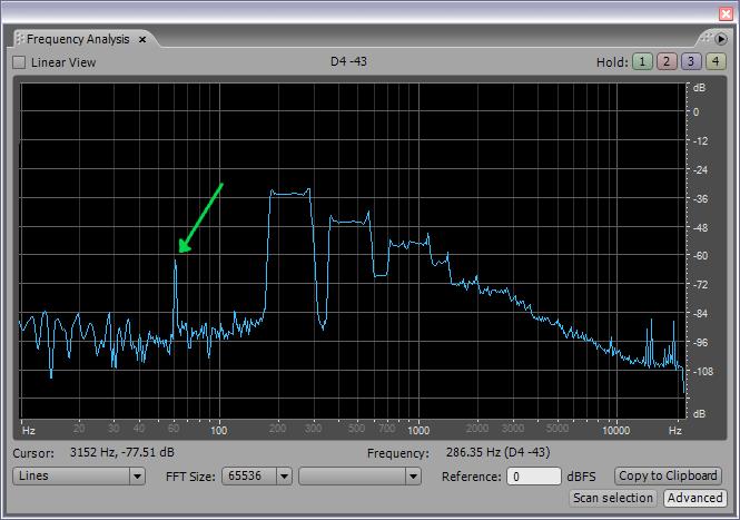
While farting around integrating the truncation filter into the CIC hum filter this morning (I don't think anything else will need it as a subroutine, and one can compute the truncation bit width using the CIC depth parameter) I wondered if I'd broken anything, so as a check I removed the hum filter from the signal path (I should note for completeness that removal of the CIC introduces 1024 / 800 = 1.28 or ~2dB of gain below, which is negligible):

Completely unacceptable spectra.  And you should see the waveform view: +/-15k peak and the hum is loud as hell in my headphones.  Numbers coming from the UART show at least a 4 bit degradation in the pitch operating point.  With the CIC hum filter in the signal path the waveform peak is +/-500, and there is no hum whatsoever in my headphones even at full volume (with a Presonus HP4 driving them that's a lot of gain at full volume!).

I'm not sure I would be inspired enough keep going much further in this project if it weren't for the squeaky clean data and relatively spur-free noise floor the CIC hum filter provides.  It's a real game changer.

Posted: 2/8/2017 10:13:09 PM
oldtemecula

From: 60 Miles North of San Diego, CA

Joined: 10/1/2014

Dew your TW anniversary will be here soon, "Come Back Over to the Light"

Then people will come to New Jersey for reasons they can't even fathom. They'll turn up your driveway, not knowing for sure why they're doing it. They'll arrive at your door innocent as children, longing for the past when electronics were warm and fuzzy. Shortwave listening will be all the rage once again.

dew said: "All Theremins Need Mains Hum Filtering In The Signal Path"

I think you mean All Digital theremins, when properly done in Analog it is not an issue. Here is my random sound sample using the noisiest switching wal-wart for evaluation. Also notice I do not have a thin digital theremin whistle sound. A fuller sound is more natural with analog.

Someday if I find a local musician I may pursue things.

I would post a picture but TW has evolved into grumpy old men... me too!

Christopher

Edit: Yes it can happen if the antenna impedance is too high, that is why we all have our favorite oscillator.

Posted: 2/8/2017 10:21:03 PM
dewster

From: Northern NJ, USA

Joined: 2/17/2012

"I think you mean All Digital theremins, when properly done in Analog it is not an issue." - Christopher

I'll stand by my statement, having experienced my EWS growling like an unmuffled Harley-Davidson due to mains hum AM/FM intermodulation.  One could conceivably lower mains hum interference quite a bit in an analog Theremin by lowering the impedance at the antenna (I've seen this on the bench, the intrinsic C and lower R form a high pass filter) but that generally hurts Q and voltage swing.  It's best, I think, to let it in the door and then immediately bang it on the head with a CIC cast iron frying pan.

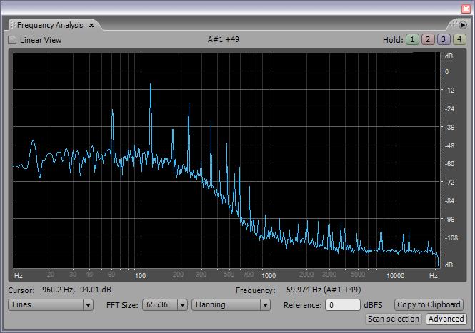
[EDIT] Here is one spectral grab of the sound sample you just posted:

Note the 60Hz hum about 30 dB below the signal.  Granted, this is the most egregious point I could find in the sample, and it's not the end of the world by any means, but who wants that mixed into (or worse, intermodulated into) their musical instrument output if it can be eliminated?

Posted: 2/20/2017 6:46:08 PM
3.14

From: Buenos Aires, Argentina

Joined: 9/14/2008

Cheers again dewster.

I came back from my holidays, with a DS1054Z in the cabin bag :)

So what I need now is the homework you promised :)

Posted: 2/20/2017 11:04:18 PM
dewster

From: Northern NJ, USA

Joined: 2/17/2012

Progress Report

Been plugging away.  I removed the operating point low pass SW filter, and redesigned the CIC hum and high pass SW filters.  Also revisited the LC DPLL SV code and simplified the constructs and  parameters somewhat.  Lots of experimentation, trying to understand the basis for the things I'm seeing via SPDIF.  Complex systems are complex, and there's much to come up to speed on, discover the nuances of, and become accustomed to.

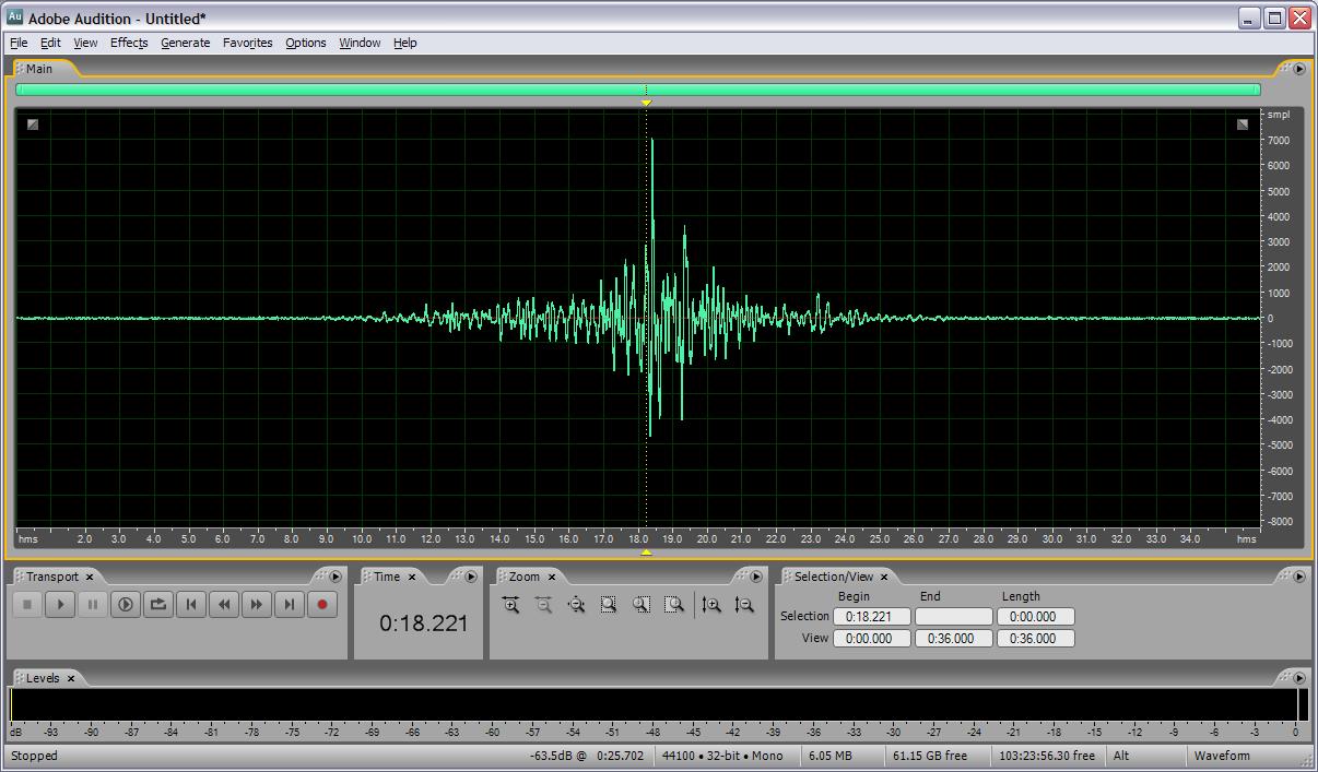
Above is the pitch operating point through just a CIC hum filter, and a first order high pass filter to remove DC.  This is me moving my hand from far away, to maybe 1" away from the antenna plate, and back.  There is an attenuation of 4 bits, 1/16, or -24dB, so that the 32 bit values applied to the 16 bit SPDIF interface are contained sufficiently to not roll over and cause false peaks.  The view above is vertically zoomed to +/-8000 or about 1/4 full scale.

The larger noise levels with my hand very near the plate are due to insufficient HP filtering (for this test) - so any small jitter on my part causes a signal; environmental noise coupling through the increased hand to plate capacitance; and perhaps a lowering of the Q as my hand parasitically draws energy off the tank, significantly lowering oscillation voltage swing.  I don't believe it will be an issue because the numbers are changing hugely when my hand is near the antenna, so even if the noise is larger, the signal is larger as well (i.e. the SNR is probably fine).

I'm getting a better feel for SW filtering; when I'm working with more than 32 bits and need two 32 bit regs to hold them, I'm now aligning the input/output with the most significant 32 bit register rather the bottom of the least significant register.  This makes the shifting manipulations clearer, and the signed ALU operations work as they were designed to.

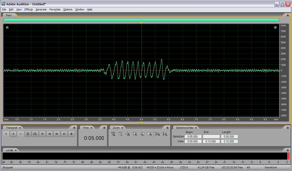
Above is full gain, with me fluttering my hand about 0.75m away from the antenna.  There's a ~15Hz component in the noise floor that's rather clear here if you squint, not sure what's causing that but I think it's environmental because it comes and goes.  The main takeaway is the ~4000 count change with only a far field hand gesture, on top of a ~600p-p noise floor (and some of the "signal" - my hand flutter - is likely being removed by the high pass filter).

Posted: 2/25/2017 9:42:29 PM
dewster

From: Northern NJ, USA

Joined: 2/17/2012

Spent the last several days rethinking and reworking Hive memory access.  The memory is indexed for 16 bit data, which is the opcode width (most processors index bytes with the address).  I had opcodes that would read and write 32 bit values, as well as read and write 16 bit values.  Since the beginning of time it seems I've been wrestling with whether the 16 bit read should be signed or unsigned (whether the read value MSb at [15] should be replicated to the upper word [31:16] bits).  Can't have both signed and unsigned 16 bit read because both operands are used along with a 4 bit index or offset field, which makes them rather expensive in terms of opcode space.

Now that I've got a fair amount of programming under my belt I decided to revisit this.  I don't find myself using 16 bit access much at all, and making subroutines to do the equivalent of 16 bit and 8 bit signed and unsigned reads are't too inefficient, so I decided to pare the hardware read down to just the 32 bit read.  This leaves room for the old 32 and 16 bit writes, as well as a new 8 bit write opcode.  Narrow width writes are more cumbersome than reads in software because they entail a read, a substitution of the relevant write data, followed by a write.  And these kinds of writes aren't atomic, so things could get jumbled in memory if some of the data changes between the read and the write back.  I had to heavily modify the main memory hardware to get this to work because the old version of Quartus that I'm using doesn't support inferred byte lane enables.  Along with this I had to heavily modify the C++ code that generates the init contents for the main memory ram (boot code).

I removed the copy byte opcodes due to disuse.  I made a new opcode - BRS or Bit Reduction Sign - which replicates the sign bit across all 32 bits.  One can do an immediate signed right 31 shift and get the same thing, but this precludes a move at the same time as the immediate value consumes the second operand select slot.  BRS is useful for normalizing floats.  I also made all the bit reduction opcodes (and, or, xor) return -1 for true rather than returning 1.  This make the bitwise NOT function correctly on their results.

It's really interesting designing a processor and tools for it - you get to do a lot of mucking around at levels few ever get to visit, and there's a lot of insight to be gained down there.

Posted: 3/2/2017 5:01:01 PM
dewster

From: Northern NJ, USA

Joined: 2/17/2012

I think I've finally fully resolved Hive memory access.  A few of days ago while washing my face before going to bed (what is it about water running that frees the mind?) I realized there are 8 modes of memory access, and powers of 2 cropping up in digital stuff generally means the universe is trying to tell us something we don't know.  So all write modes, as above, are 32 bit, 16 bit, and 8 bit.  And all read modes are 32 bit, 16 bit signed and unsigned, and 8 bit signed and unsigned.  What's a bit peculiar is the read/write division isn't binary (3 writes, 5 reads), also 8 bit access isn't "natural" in the sense that the smallest addressable unit of data is 16 bits (the opcode width) so 8 bit access somewhat awkwardly relies on the immediate (a value carried in the opcode) index to resolve the high or low byte.

Reads and writes had four bits of immediate indexed positively offset memory locations. None of my code up to this point needs anything like 16 read / write slots, so removing an immediate index bit allows for the increase from 4 to 8 memory access opcodes with 8 indexed locations each in the opcode space, which seems adequate.  I really liked the index being a nibble, but that probably hindered the exploration of other possibilities in my mind.

I made the necessary changes to the simulator and assembler, wrote some HAL code that exercises all the corner cases, got the last SV bugs out last night, and verified everything in the chain.  The extra logic required to do this isn't much at all, and after jiggering the decode order it doesn't seem to negatively impact the top speed either.

So why don't I just make the memory byte addressable?  The logic is substantially there to enable it, and many (most?) other processors do this.  In my mind it comes down to the relative utility of byte data vs. opcodes.  Byte data is used rather heavily in text and vision/image software, so it makes sense to accommodate them in the hardware.  But basing the addressing on them is a bridge too far IMO, because it means you have to think of two different address spaces when coding, one for data bytes and one for 16 bit opcodes.  Do you allow for opcodes that are offset by a byte (how might this be useful)?  Or do you just ignore the LSb?  Either way the the instruction address space shrinks by 1/2.  How about jump distances, are they byte or 16 bit based?  Byte based consumes precious immediate index space.  Byte indexing of memory isn't a panacea, bytes themselves don't carry a ton of resolution, and memory tends to be pretty cheap these days (though not inside FPGAs).   So many processor decisions are compromises, but maybe I've thought enough about this to finally feel at peace with it all.

It's semi-major structural changes like this that make me glad I'm coding for Hive in assembly, rather than binary.  Accommodating even something like a complete scrambling of the opcode space essentially comes down to a simple re-assembly of the old code.

Posted: 3/8/2017 3:43:43 PM
dewster

From: Northern NJ, USA

Joined: 2/17/2012

Working on the command line interface (CLI) again.  I really miss it, and really need it to peek & poke memory, run hardware exercise scripts, and the like.  The one I wrote and was using was somewhat awkward - in particular the backspace key didn't work like you expect so there was no way to fix single keystroke errors.  I've done this kind of investigation before, but yesterday I got really serious and recorded all the codes that are produced in the text terminal via C++ getch() when the PC keyboard keys are pressed, stuck them in a spreadsheet, and sorted them:

http://www.mediafire.com/file/8f0dch71a1z8i8y/ascii_getch_table.xls

There are lots of these kinds of documents on-line, but I've found most of them to be rather untrustworthy / not filtered through a Windows-centric development environment.

Also included in the spreadsheet is a worksheet table with four-column ASCII, with vertical least significant hex nibble values and horizontal most significant hex nibble values.  This nicely shows the repeating nature of the ASCII character encoding.  Hex is the best way to view, list, and understand ASCII encoding, I'm not sure why coders often use decimal here as it obscures the underlying symmetry.

But an ASCII table doesn't tell the whole story of what's going on in terms of keyboard output, hence the need to document actual getch() data.  It's a matter of input vs. output, there are way more key combinations (with SHIFT, CTRL, and ALT) than there are ASCII characters to display.  The excess input combinations are handled via escape characters.  The original IBM PC keyboard used the value zero (0) to indicate escape, with the following character interpreted differently than normal, and a reversion to normal interpretation after that character.  The IBM 101 PC keyboard added a second escape character 0xE0 to handle the new page navigation pads.  So these have to be accommodated somehow in a full CLI implementation.

Almost all keyboard generated codes are in the range 0 thru 127, which is an unambiguously (whether signed or unsigned) positive byte.  And the escape characters don't show up as escaped data, which makes things easier - if you encounter them they definitely are escape characters, so you don't have to look from the beginning of time to know what the current state is.

Because my hardware doesn't interface to it, I haven't done any investigation into what codes are actually emitted by the keyboard hardware.  I do know the keyboard serial interface is bi-directional, and there are ways to determine when multiple keys (beyond the usual SHIFT, etc.) are being depressed / lifted. 

ASCII, keyboard codes, the way they are interpreted by the OS and programming language libraries, and the whole English-centric thing, are a big steaming pile of legacy, hence the need for rosetta stones here.  (If I were in charge of straightening this mess, at minimum I'd make the ASCII codes for the characters 0-9 and A-F correspond to their hex values.  As it is the ASCII code for the zero character is 0x30, and the code for the letter 'A' is 0x41 - crazy stuff.  It could be a whole lot more crazy, but it could be a whole lot less crazy too.)

[EDIT] Holy Moses!  The scan codes coming out of the keyboard hardware serial port are one serious mess!  Check this out: http://retired.beyondlogic.org/keyboard/keybrd.htm
Posted: 3/16/2017 10:14:02 PM
dewster

From: Northern NJ, USA

Joined: 2/17/2012

Just got the key and token buffers assembly code working on the FPGA board.  I'm seeing a lot of VT100 escape characters that I didn't anticipate. For instance, pressing the F1 key gives the string [11~ which is sorta weird.  Outside of the main QWERTY pad only ESC, BSKP, DEL, and on the number pad 0 thru 9, the decimal place, and ENTER give ASCII codes.  The rest of the keys give these goofy escaped strings. So much for using the function keys in my command line interface.  And so much for accommodating the escaped getch() codes, I don't believe any of them get transmitted normally by the terminal emulator.

So it's time to integrate the command part of the loop.  I'll likely retain the FORTH like <#> <#> ... <#> <@> command format, where # is a numeric parameter, and @ is a non-numeric parameter / command.  Numeric parameters are C-like, with 0x hex prefix and the like.  The command is executed when the non-numeric parameter is recognized, and can vary depending on the parameter count. Commands can be up to 4 ASCII chars beginning with a non-numeric char and followed by space or return, or followed by nothing in the case of things like backspace and escape.

I'm having to flow chart the parsing in order to have something to follow and not freeze-up when coding.  There are so many what-if scenarios and only so much room in my brain.

Posted: 3/29/2017 10:09:19 PM
dewster

From: Northern NJ, USA

Joined: 2/17/2012

Variable & Immediate SEX!

Now that I've got your attention... Sign EXtension, that is!  And its partner in crime ZEX, or Zero EXtension - both are bit modulo operations that can force register values to behave in a modulo manner smaller than the natural modulo of register width of 32.

Spent a pleasant last week in an enclosed lean-to in Stokes State Park here in NJ and had some time away from the internet and other distractions to really think through various Hive things.  I thought I hit on a really innovative opportunity - the fetch port is only 16 bits wide but could easily be 32 bits and supply a 16 bit in-line immediate, freeing up the 32 bit data port for other things.  Opcodes are already variable width in a way, with 0, 1, or 2 - 16 bit literals following them, so this wouldn't be all that new.  And using byte addressing would allow for an 8 or 16 bit literal, potentially raising utilization efficiency.  It seemed like a fantastic thing for a day or so, but seemed less so after hammering out possible implementation details.  The expanded opcode space would allow for more and varied opcodes, with and without expanded immediate values and operands, but the various groups would have to be encoded in such a way as to be fairly orthogonal, and thus easy to decode.  Alas, I fell out of love with the notion, there were just too many new datapaths, and two value comparisons are a can of worms.  I think the current rather limited opcode set now available is sufficient to do just about anything, and it's pretty easy to keep in one's head.

The upshot though is I decided to remove the 16 bit and 8 bit memory read modes, and implement both variable and immediate sign extension and zero extension opcodes to take up some of the slack.  I also reduced the memory access immediate offset to 3 bits, and expanded the immediate multiply to 8 bits.  This leaves a couple of holes in the opcode decode space for future additions.  I might expand the immediate add to 9 bits, or the smallest immediate load value to 9 bits (to cover both signed and unsigned 8 bit values).  We'll see I suppose.

It was interesting implementing the ZEX and SEX opcodes.  There was the basic question of exactly how the sizing input modifies the data: should the sizing value specify the input data width to preserve, or should it specify the MSb to replicate to higher bit positions (in the case of SEX)?  I chose the latter because it seems a bit more useful.  So a size value of 7 for example will preserve a byte and zero / sign extend the higher bits.  A size value of 0 will preserve the LSb and replicate it to the full vector (again, in the case of SEX), and a size value of 31 will leave the data unchanged (for SEX or ZEX).

Zero extension can easily be done in a single clock (<5ns) but sign extension requires decoding of the given MSb location, with replication similar to ZEX after, which barely fits in a single clock and slows other things down.  So I decoded the MSb value and registered it, implemented both zero extension and ones extension, registered them, and picked the right one for the ZEX output based on the registered MSb value.  The muxing worked out rather cleverly with the existing muxing.  The basic core is now up to 2760 LEs, and hits 194.7MHz on a short seed run.

You must be logged in to post a reply. Please log in or register for a new account.