Let's Design and Build a (mostly) Digital Theremin!

Posted: 5/5/2018 5:05:39 PM
dewster

From: Northern NJ, USA

Joined: 2/17/2012

Rocket Surgery

Yesterday, Hacker news (link) pointed to Akin's Laws of Spacecraft Design (link) and I was particularly struck by #4 and #20:

4. Your best design efforts will inevitably wind up being useless in the final design. Learn to live with the disappointment.

I've experienced this quite a lot in this project, there's not much you can do about it as many ultimately blind / not-applicable alleys must be followed to their logical conclusions.  Doing extra research slows the project down, but isn't always disappointing or painful (reading research papers can be extraordinarily fun) and you never really know where your next implementation idea will come from.

20. A bad design with a good presentation is doomed eventually. A good design with a bad presentation is doomed immediately.

I've given this quite a bit of thought lately and really have no idea as to how to handle it.  I want to show (via video, sound clips, etc.) what the prototype can do, but I know I'm not the best player (there's a reason they hire Elton John et al to play keyboard demos at NAMM) and I'm often demonstrating half-baked engineering results in a somewhat rushed manner.  I fear I'm turning a lot of potential future customers off, but what do you do?  I suppose I'm more interested in finding and presenting solutions to the various engineering stumbling blocks associated with digital Theremins & vocal synthesis than I am in making a big splash with the next iWhatever.  Though I do understand why companies keep products under wraps until the "black eye" phase has passed.

[EDIT] I'll just leave #1 here:

1. Engineering is done with numbers. Analysis without numbers is only an opinion.

Posted: 5/8/2018 4:34:11 AM
dewster

From: Northern NJ, USA

Joined: 2/17/2012

Aliasing Is Really Weird

I remember reading about aliasing in Hal Chamberin's book "Musical Applications of Microprocessors" and thinking he must have it wrong, or I must be reading it wrong, or something - the world can't be that crazy.  I figured "I'll just generate the wave, and if that gives me trouble I'll filter it, and if that gives me trouble the worst I'll have to do is generate it at 2x oversampling, filter it, and downsample."  The crazy harsh truth is you can't digitally generate anything but a sine wave and not have it alias all over the place without going to great lengths, because in a very real sense you are "sampling" a continuous wave in the sampled realm by the mere fact of generating it, even if at each sample you're doing everything perfectly.  There's no way to filter the aliasing away after you generate it, which is really counter-intuitive.  But there are mechanical ways (fractional filters, injecting gibbs phenomena type ringing, etc.) to ameliorate it, which is also really counter-intuitive.  Why do mechanical methods work but filtering methods don't?  

I don't know exactly, but wonder if it has something to do with the non-ideal behavior of the digital differentiator.  The digital integrator works as analog ones do, but the gain of the digital differentiator drops off near Nyquist, and then reverses afterward.  I've read people saying this, but I never really understood it until this morning.  When you have almost 1/2 a wave in the differentiator, the gain is dependent on the shape of the wave, which is a sine, which is non-linear.  And this, I believe, is why sine shows up as an error term in digital filter tuning.  DSP people must know these things, but they rarely just blurt them out.

On top of this, musically interesting waveforms tend to have a lot of harmonics, and they generally fall off slowly at 6dB/octave / 20dB/decade, so when you go for that >1kHz fundamental you get a pile of harmonics with significant energy hitting Nyquist (1/2 the sampling rate) and folding back down right into your lap.  And all of the solutions / ameliorations to this are fundamentally problematic in one or more ways.  They work, some better than others, requiring things like big tables in memory, odd calculations, strange thresholding/detection, switching in and out over various ranges, variable gain over a large range, leaky integrators, etc.  There's no "THAT'S IT!" solution.  Part of the strategy often seems to be picking the top note on the piano as the upper limit and calling it a day.

[EDIT] "There's no way to filter the aliasing away after you generate it" - this isn't true actually.  You can use a tracking comb filter, either FIR or IIR, to lower inter-harmonic aliasing, and a high pass filter can lower the more audible aliasing below the fundamental.  But comb filters take memory, and you need a fractional delay element in there, as well as a way of switching the delay without glitching.

Posted: 5/8/2018 9:46:04 PM
dewster

From: Northern NJ, USA

Joined: 2/17/2012

CIC Interpolation

I pretty much understand CIC decimation, which lowers the sampling rate.  The opposite of this is interpolation, which is used to "fill in the blanks" when increasing the sampling rate.  A CIC interpolator is a series of N differentiators, a zero-stuffing up-sampling "switch" which closes for one sample every R samples, followed by N integrators.

What was getting me was the switch and the first integrator following it. If you feed an integrator zeros it just sits there holding it's value (a "zero order hold" in the lingo) which means you can pull the first integrator back through the switch and run it at the lower source rate and get rid of the switch. And now the last differentiator and following integrator should cancel!  So an Nth order CIC interpolator should only require N-1 differentiators and integrators, and no zero stuffing switch.  Am I losing my mind?  There's no mention of this in Hogenauer's paper, which seems like a huge oversight if true.

Indeed, it is true: https://www.dsprelated.com/showthread/comp.dsp/368488-1.php

Many other hardware saving tricks like this in the fantastic paper "Reducing CIC Filter Complexity" by Ricardo A. Losada and Richard Lyons, IEEE SIGNAL PROCESSING MAGAZINE [124] JULY 2006.  Just more fundamental DSP stuff no one bothers to mention...

Posted: 5/13/2018 5:29:49 AM
Martel

From: Russia

Joined: 9/8/2016

Видео по теме;

https://www.youtube.com/watch?time_continue=384&v=UHTF1-IhuC0

Posted: 5/13/2018 1:49:28 PM
dewster

From: Northern NJ, USA

Joined: 2/17/2012

Shaken Harmonic Syndrome (Dither)

Thought I was onto something but it has issues that aren't easily surmountable.  The way I'm getting a spectrally pure square wave going to the antenna tanks is by applying one sample cycle's worth (amplitude) of white phase noise, or dither, to the phase accumulator (but we don't actually accumulate it because that would give us a Gaussian noise amplitude distribution rather than rectangular).  It was something of a mystery to me how this actually works but it's clear now that I'm investigating audio alias suppression.  To wit: harmonics at Nyquist (1/2 the sampling rate) "live" in exactly two samples (or cycles), and harmonics higher than this "live" in less than two samples.  Adding 1 cycle's worth of phase noise to the waveform causes everything "living" in two samples or less to average together.  However, as you might imagine, this raises the noise floor.  And higher fundamental tones have more harmonic energy at and above Nyquist, and so they have a higher noise floor when dithered.  Viewed another way, the added dither noise has to be scaled (multiplied) with the frequency in order to kill aliasing, and this increases the noise floor for higher fundamental tones.

On the audio side of things, using white dither I can generate a ~250Hz sawtooth that sounds pretty good, but above this the dither noise starts becoming obvious, until at 8kHz the tone is drowning in noise.  One could spectrally shape, or filter, the dither to be outside of the area of the most sensitive human audibility but still below Nyquist in order to make it less obvious.  One could also use a tracking high pass filter to suppress the noise below the fundamental.  One could certainly generate things at an oversampled rate, and the dither would scale down with the oversample ratio (OSR).  8kHz / 250Hz = 32 OSR which is a lot of calculations to do!  One could certainly combine milder OSR and noise shaping, the OSR region would give plenty of dither room above audio but below Nyquist, but then we're doing more calcs at a lower rate - no free lunch, it's all a trade-off, with some worse than others.

While researching dither I ran across the rather mis-named "subtractive dither."  Here one injects dither at one point, quantizes, and then subtracts the same dither downstream.  Something one can easily do within a system, but not so easily between systems as the dither signal would need to be replicated and synchronized.  To subtract the injected phase noise post NCO accumulator (quantization) one would need a linearized variable sub sample delay, and this element can be problematic.  It seems feedback (IIR forms) can't be used because the delay is changing quite dynamically with each sample, and higher orders based on spline interpolation are necessary to sufficiently reduce variable delay with frequency (group delay).

Which brings us more or less to the poly-BLEP method of alias reduction.  Here the naive saw edge is fractionally delayed based on the phase accumulator error, and Gibbs phenomena ringing is also injected, both of these via a short polynomial based spline FIR filter.  It sounds more complicated than it boils down to, but there's a fair amount of engineering involved behind the scenes.

Posted: 5/17/2018 12:17:59 AM
dewster

From: Northern NJ, USA

Joined: 2/17/2012

It Was Necessary To Destroy The Precision In Order To Save It

I read an article yesterday regarding the writing of early space software, where the processors were asthmatic and had no floating point hardware.  Seems they spent 30% of the time just managing precision, which is much better than my ratio!

For the last couple of days I've been trying to implement a toy NCO (numerically controlled oscillator) that employs a fractional delay to align the sawtooth edge, which happens at accumulator rollover, and the value in the accumulator at rollover gives the fractional delay if you divide it by the phase increment (normalize it).  So we need the reciprocal of the phase increment, which calls for the dreaded integer division, where precision basically goes to die.

Premature optimization, but I pared the Newton's method integer quotient and remainder subroutine down to give just give the reciprocal, which is 22 cycles max.  The precision issue raises its head when you feed it larger integers, which give very small fractional results.  Give it 32 bits and you get 0 bits, give it 0 bits and you get 32 bits, so the happy medium seems to be 16 bits, but it really depends on the range of the input data.

Given a 32 bit accumulator, to generate 32Hz at a 48kHz sampling rate we need a phase increment of (32 / 48k) * 2^32 = 2863311, which is 21.5 bits of info, taking the reciprocal of this gives 10.5 bits of info, and we have to take the worst (10.5 bits) here for the precision (garbage in/out).  To generate 8kHz the phase increment is (8k / 48k) * 2^32= 733007751, which is 29.5 bits of info, which means the reciprocal only has 2.5 bits of info!  Shifting the phase increment to the right 10 bits obviously throws 10 bits of input info away, but increases the minimum precision of the reciprocal.  Over the 32Hz to 8kHz range this shift gives a precision of 15.5 bits over the middle range and 12 bits at the extremes, which should be sufficient for this application.

[EDIT] So I used the above to reduce aliasing and it does work.  I can get a clean sounding sawtooth up to ~1.4kHz.  Need to try it with 8x oversampling. One nice thing about that is the reciprocal is a constant over the oversampled period.  Not sure where this is going as I really like the phase modulated sine wave approach, and I don't think this method of alias reduction adapts well to that.  I'd like a generic process that is continuous, just feed it anything and have it kill aliasing without looking for edges, but I'm not aware of any process that can do that.

[EDIT2] Here's the sawtooth NCO:

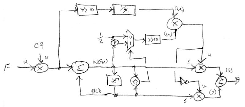
The frequency (phase increment) comes in and gets scaled to C9 max.  The upper path shifts it right 10 places to trade 1/x precision, then 1/x is called (unsigned).  The middle / lower path accumulates the phase increment, producing old and new values, which are compared (signed) to detect the sawtooth edge.  If so, 1/2 (2^31) is added to the new to make it unsigned, whereupon it is shifted right 10 places to match 1/x, then the two are multiplied together (regular, not extended multiplication, which is sign agnostic).  The resulting unsigned value is use to crossfade between the old and new NCO values, and the result is the output sawtooth waveform (signed).  When there isn't an edge the old and new get averaged together, which gives us a filter zero at Nyquist.

The NCO accumulation value can be seen as signed or unsigned, but you have to be consistent or it won't work (ask me how I know this).  As with PLLs, I get easily confused when it comes to "error" vs. "correction" signals.

Lately I'm coding up NCOs and commenting all but one out, and recording the audio of the variations in one audio file, comparing the sound, waveforms, and spectra in Audition, an arrangement which is working out well.  Otherwise it's hard to keep it all straight.

Posted: 5/19/2018 8:28:33 PM
dewster

From: Northern NJ, USA

Joined: 2/17/2012

Casio Patent

I suppose most people looking into this kind of stuff have seen the old Casio waveform synthesis patent: (link).

It's really simple and fairly ingenious.  They generate the usual NCO ramp and use it as cosine phase (via a ROM lookup).  But they modulo multiply the phase ramp so as to get more than one wave per period.  To kill discontinuities at the start and end (if the waves per period are not an integer multiple of the base period) they make the cosine unsigned and starting at zero, then they multiply it by the logically negated base ramp (to make the ramp fall rather than rise), or with an unsigned triangle formed from the base phase ramp.  With this they can get fairly what I think of as "molar" looking waves - humps with bites taken out of them, often associated with Theremin and formant stimulus.

[EDIT] I simulated some of the Casio waveform synthesis in an Excel spreadsheet, both triangular and raised cosine AM:


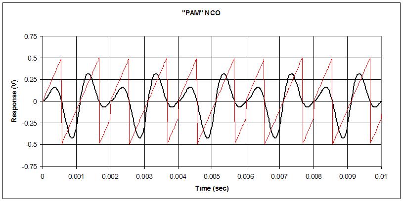
Top: The waveform (heavy black line) and NCO phase (thin red line) are shown for a fundamental of 500Hz with 1.9 cycles per cycle, triangular AM.  Note the nice "molar" shape.  Unlike in the patent, I'm using a signed sine wave as the base wave, rather than unsigned cosine, which mostly gets around the DC offset issue.

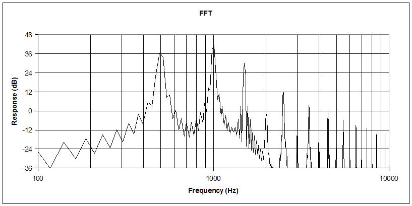
Bottom: Resulting FFT (2048 points with triangular window).  Note the suppression of even harmonics starting at the 4th.

I played around with phase offset but it didn't seem to make much difference to the FFT.  Raised cosine AM makes the harmonic amplitudes more uniform - perhaps more boring?  Now to try this on the prototype and see what it sounds like...

Posted: 5/21/2018 2:53:46 PM
dewster

From: Northern NJ, USA

Joined: 2/17/2012

Casio Patent - continued

OK, coded up the phase & amplitude modulation (PM & AM) techniques in that patent and tried them out on the prototype.  All three sound like a tracking filter, with increasing number of cycles per cycle (the cycle multiplier) sounding like stronger (higher Q) tracking.  

To my ears, raised cosine AM is the least musically interesting.  It's really smooth sounding, with higher harmonics diving to zero.  You can get the first two harmonics and nothing else if you want that; or the first three; or the second, third, and fourth and nothing else.  Settings in-between give the rest of the harmonics, but their amplitudes are kind of low.

Reversed ramp AM could be fairly useful if you didn't otherwise have a tracking filter, as it moves the emphasis (harmonic peak) from the fundamental to the higher harmonics.

Triangular AM gives the most variety of sounds.  Setting the phase multiplier to less than one gives all harmonics falling off at a fairly quick but even rate, it could probably be brightened with a filter and used to stimulate vocal formants.  Setting it really low gives odd harmonics.  Setting it to 1.5 gives rather human sounding vocals without formant filtering.

==============

Rethinking C9 Max

The top octave on the prototype ends on C9, which is 8.372 kHz.  This is one octave higher than a piano goes and it's a tough octave from a couple of synthesis angles:  It's obviously really hard to eliminate aliasing that close to Nyquist, and it limits the lower end of the Q range for the second order filter I'm using.  So I'm thinking of lopping it off and going with C8 max.

Posted: 5/25/2018 12:52:31 AM
dewster

From: Northern NJ, USA

Joined: 2/17/2012

Encoder Debounce

One of the encoders has gotten so flaky I can barely use it.  Turning it CCW at any significant rate causes it to do the opposite thing at a huge rate!  I've gotten away up until now with no real debounce, just resync and routing it to a simple Gray code counter based state machine (running at 180MHz!).  So today I thought about, coded, and added debounce logic to each encoder lead (8 encoders with 2 leads each = 16).  You can't save logic and debounce the 2 leads together, and I believe the best solution here is true debounce, and not just a stability time updater.


The input is resynced via a short shift register, then combined with an up/down counter max and min based on the 3 MSbs.  This gives ~3/4 of the total range, and also nice ~1:1:1 sized hi/no_change/lo hysteresis range.  The associated MSbs are [011], [001], [110], and [100] for (signed) max, hi, lo, min.  The minimalistic decoding reduces the logic and really speeds things up.  Then the output is updated based on the hi/lo counter range.

With an 8 bit counter it's working like a champ!  The flaky encoder seems to be quite well behaved now, and the rest are doing their usual fine thing.

Also, in the software I went ahead and set the max frequency of the oscillator and filters to C8, which is 4.186kHz.  For the filters this is right at the edge of being able to do the upper female formant, so I may address it again at some point.  Maximum damping for the filters is now 2.0 (it was 1.0) and stable for any frequency setting.  Perhaps counter-intuitively, higher damping requires more feedback, of which the corner frequency is also a factor.  So max frequency and damping is where you will encounter instability (if it exists).

Posted: 5/25/2018 5:09:41 PM
dewster

From: Northern NJ, USA

Joined: 2/17/2012

BLITs and BLEPs and DPWs (Oh My!)

Having delved into the various alias reduction methods I thought I'd summarize them.  These are methods to generate the standard analog synth waveforms (triangle, sawtooth, square) with reduced aliasing.  The main "trick" behind all three is in exploiting the extra information one has about the ideal waveform (as it exists in the continuous amplitude and time space, such as analog) and utilizing this to construct something that is close to the sampled and band limited (digital) representation.  I haven't actually done any BLIT or BLEP in practice nor in simulation.

I encountered BLIT (Band Limited Impulse Train) and BLEP (Band Limited step function, not sure where the "EP" comes from) on various coding sites, but it seemed the coders were mostly blindly following instructions from papers and copying each other, so there was little insight to be gained from their resulting floating point code. 

With BLIT they generate (via tables or polyphase FIR filter) a SYNC-like train of impulses (periodic spikes that have Gibbs Phenomenon "ringing" leading up to and trailing the spike).  The impulses themselves are largely band-limited, so a string of positive ones can be "leaky" integrated to form ramps, but the leakage here must scale with frequency.  An alternating string of positive and negative impulses can be simply integrated to form square waves (here minor constant leakage is used only to get rid of any DC bias).  

With BLEP they concentrate on reducing the aliasing of instantaneous steps in the end waveform.  The approach is very similar to BLIT (with tables or polyphase FIR filter) but they instead generate ringing, band-limited edges and merge these with the naively generated desired waveform.  The polyphase filter approach can be quite efficient and effective at alias reduction.

Both BLIT and BLEP use the phase error information in the phase accumulator immediately after a modulo roll-over to fractionally position the output edge, which kills a good portion of the aliasing, and the Gibbs ripples lower it further.  And if you think about it, this phase error isn't something you can trivially intuit after the fact.  Running the naive (quantized) edge through a low pass filter will just average the positive and negative points, always returning a point that is roughly centered at zero, when what you need is a point that is more positive or negative based on the quantization error sign and magnitude.  So THIS is why simple low pass filtering can't get rid of aliasing.

With DPW (Differentiated Parabolic Waveforms) they recognize that, over the cycle, a ramp is just a line with a slope.  Mathematically integrating it gives x^2, or a parabola.  If we then differentiate this (i.e. the phase ramp value squared) with a DSP filter type differentiator, a reduced alias ramp is produced, seemingly by magic!  To better understand what's going on here I simulated it in Excel and compared the results of mathematical integration to DSP filter type integration.  Again, the "trick" is that mathematical integration includes extra information about the phase that the filter type integration doesn't, and this info helps to fractionally position the sawtooth edge.  A problem with this approach is that aliasing isn't eliminated, and this forces one to higher order mathematical integrations and more DSP differentiations.  Which seems OK, but mathematical integration doesn't have the gain associated with an integration time constant, so one must scale the result 20dB (10x) per decade per order, which can really add up.

One of the simplest approaches is to comb filter (FIR or IIR) any aliasing in the gaps between the harmonics, and below the fundamental.  The problems with this are that you have to know up-front if the waveform contains only odd or all harmonics, and the fractional delay filters employed are somewhat dispersive (non-harmonic) so they will interfere to some degree with the harmonics themselves.  And the filter requires as much delay memory as the lowest fundamental you desire to put through it.

============

In the end, I'm pretty happy with my phase distortion-based oscillator.  It gives me continuous and dynamic control over the slope of the harmonic roll-off, as well as all/odd/no harmonics, and doesn't alias too bad.  And if I want screaming cats I can just use a tracking filter.

[EDIT] In a way, I think it's maybe a mistake to try to replicate what's going on in the analog synth world with 100% fidelity.  If you want harmonics you can get them in many ways, and resulting waveforms don't have to even remotely look like the analog classics.  I mean, those waveforms were picked mainly because they're relatively easy to generate with standard circuitry and such.

I must say, this exercise has got me thinking about harmonics in new ways.  e.g. instead of clipping to get harmonics, maybe just run an amplitude-based control over the harmonic content input.

You must be logged in to post a reply. Please log in or register for a new account.