Let's Design and Build a (mostly) Digital Theremin!

Posted: 10/11/2018 11:54:57 AM
pitts8rh

From: Minnesota USA

Joined: 11/27/2015

I did order everything that I didn't already have, including the 7-segments, but I'm thinking I have a couple Toslink modules in my parts.  If not, I'll get back to you.  I probably don't need 25 from Electronic Goldmine.  I even bought two FPGA boards just to prove I'm all in, baby!  I ordered the 20x4 display from the same source as you, so if you got the wrong board I may have the same problem.  When the time comes I may have to ask you what the problem was and what you had to do to modify it...

Since there are a couple things here that are totally new ground for me, particularly in the FPGA side, I will be attempting to initially build everything as specified to eliminate too many variables.  If/when that is up and running I will go off on my own and experiment with the oscillators/antennas, one thing at a time.  I didn't order wire because I have these and several other gauges already.

While I'm waiting on parts I'll watch for your schematics (no rush), but I've still got plenty to do with the CNC project from hell (so I can drill boards) and a couple other projects.  Oh yeah, and acres of leaves to clean up soon...

Posted: 10/11/2018 2:59:01 PM
dewster

From: Northern NJ, USA

Joined: 2/17/2012

The Toolsing

Roger, here's the tools side of things:

Get the FPGA tool Quartus: https://www.intel.com/content/www/us/en/programmable/downloads/download-center.html.  I use version 10.1sp1 (the free web edition) to compile the SV code and pump the board, and to update the blockram Hive ROM default boot code.  (I also use 9.1sp2 as this is the unfortunately last version that has the simulator, but you won't need that unless you want to dig into the actual FPGA logic.)  I'm hoping that counterfeit USB Blaster doesn't give you any trouble (all this stuff should be open sourced IMO).  Some versions seem to rely on a cloned Prolific USB serial bridge chip which is unfortunate because Prolific started a driver war over it, and we all get caught in the crossfire.  Same for the USB serial TTL cables, it's a mess.  I hear FTDI plays nice.

For programming the EEPROM chip via the serial port, I'm using Tera Term Pro version 4.81 (I see it's up to 4.100 now):  https://osdn.net/projects/ttssh2/releases/.  It has a "TTL" macro language that I use to manage the CLI port handshaking.  My Hive simulator automatically kicks out a "hive.ttl" file that you just run (Control | Macro) in order to update the SW load.  Port speed is 230400 baud, 8N1, no local echo.  When you get the USB serial TTL cable try sticking a low value resistor or wire between TX and RX and see if you get an echo in the Tera Term console.

The Hive assembler / simulator runs fine in my WinXP console, but I've noticed on Win7 machines the UI interaction is pretty sluggish.  It may be that It's running 32 bit C++ code rather than 64?  The newer Win console seems very different.  Something I should work out on my end now that I've got a Win10 laptop.  I assume you're not running WinXP?  [EDIT] Here is my latest Hive sim C++ code and Theremin HAL assembly code with a compiled 32 bit simulator included: https://www.mediafire.com/file/789x49armcbt91a/2018-10-11.zip/file

I'm using Notepad++ as my HAL code editor: https://notepad-plus-plus.org/ which is an absolutely fantastic editor.  I've got a color & highlight scheme just for HAL that you can import: https://www.mediafire.com/file/b229v5gy8c4vau4/notepad_plus_hal_defs.xml/file.  Setting the tab size to 36 or so makes HAL code more readable.  You can set things up so that opening a *.hal file uses the color scheme and tab spacing.

The LCD display people (eastrising) are telling me that is the 100% 3.3V version, but there's a bit of a language barrier (though they are quite responsive and friendly seeming).  You should be able to instantly tell just by looking at the back of it when it arrives.  Still no response from the 7 segment display dudes.  [EDIT] I'm told by the sellers that the 7 segment is common anode; the listing title was accurate, the details not, so that should be OK too.

Posted: 10/11/2018 5:20:11 PM
pitts8rh

From: Minnesota USA

Joined: 11/27/2015

 When you get the USB serial TTL cable try sticking a low value resistor or wire between TX and RX and see if you get an echo in the Tera Term console

I'm reading this thinking "what USB serial TTL cable?".  It was late last night when I was ordering parts furiously, and I guess I wasn't paying much attention to what I was ordering.  Turns out I think I have a couple of these already, somewhere.  It's a good thing you didn't slip any prank links in there.

I have WinXP as my utility bench laptop, with 7 32bit and 10 machines within reach.  Already use Notepad++, too.

Posted: 10/11/2018 7:10:12 PM
dewster

From: Northern NJ, USA

Joined: 2/17/2012

"It was late last night when I was ordering parts furiously, and I guess I wasn't paying much attention to what I was ordering. ...  It's a good thing you didn't slip any prank links in there."  - pitts8rh

When the Interocitor kit arrives, tell the big giant headed dude on the screen I said "hi"  ;-)

"I have WinXP as my utility bench laptop, with 7 32bit and 10 machines within reach.  Already use Notepad++, too."

Wow, I can't imagine running into anyone else quite as ready / able / qualified as you to do this.  An EE with a full home lab & fab shop - and you're a fantastic guitarist!

Note the [EDIT] above, I put the compiled Hive simulator in the zip file along with my HAL assembly and sim C++ code.  Unzip it to a folder and make a shortcut to "hive_sim.exe".  Right click on the shortcut and click the "Options" tab, set "Command history" "Buffer size" to 48.  Click the "Font" tab and pick 8x12 raster fonts.  Click the "Layout" tab and set both "Screen buffer size" and "Window size" to 128 x 48.  Apply and close, then run the shortcut to see if everything is OK.  

The function keys select the thread to view (F8 = thread 0), up/down arrows move one line at a time, page up/down a page at a time, home returns to the execution line.  F10 single steps, the command "isr" without quotes and with a space at the end issues an interrupt to the current thread.  Since everything in the Theremin software is interrupt driven you need to single step a bit until the thread parks, then issue an isr, then single step some more to see the isr code being executed.  If you input a number, say 100, and press F11 it will do 100 cycles every time you  press F11.  F9 is a single clock step (8 per cycle).  Input an address and press F12 to run to breakpoint.  Escape stops infinite loops and such.  

To reload the file and reset the sim do a "cfg" command, and you can specify a different source file before the command if you like.  "theremin.hal" is the current hard coded default source, and it pulls in a bunch of others in that directory.  Generated in that directory whenever you open the sim or do a "cfg" is "hive_0.mif" thru "hive_3.mif" which are FPGA blockram config files, which can be copied to the FPGA directory (I've got a batch file that does this).  Also generated is "hive.ttl" which is the Tera Term macro to pump the EEPROM.

Posted: 10/11/2018 8:59:45 PM
dewster

From: Northern NJ, USA

Joined: 2/17/2012

The Hardwareing: AFE

The AFE (analog front end) takes a square wave drive from the NCO (numerically controlled oscillator) inside the FPGA, buffers it, drives the LC tank, reduces the voltage and squares up the resulting large amplitude (hundreds of volts) sine wave, and then sends the result back to the FPGA.  It also sends back a buffered reference in an attempt to null out any temperature dependent delays, and the phase of these two signals are compared.  The DPLL (digital phase locked loop) logical construct in the FPGA constantly adjusts the NCO frequency to maintain a quadrature (90 degree) phase difference between them, as this is the peak resonant point for the LC tank where we get maximum voltage swing, as well as the most "phase gain" between the two signals.

The AFE is identical for both axes, though different coil values are used to keep the operating points (frequencies) spread apart enough to keep  them from seriously interfering with each other.  And of course each employs a separate DPLL.  Additional logic inside the FPGA takes the NCO number, low pass filters it, and downsamples it to 48kHz, whereupon it is further conditioned, the hum removed, offset, scaled, and linearized, for pitch and volume use in the synthesis engine.  So the values are obtained directly, and there is no heterodyning going on.


Above is the AFE circuit shown two different ways.  The upper view is more schematic, the lower more of a component layout view.  In the lower layout view note that the signal drive side also "drives" the ground, but the ground on the receive side is not connected.  This is done to eliminate ground loops, and for signal integrity purposes.  The interconnect wires are twisted pairs in the CAT5 cabling.  There are 4 pairs, one is used for drive, two are for sense, and the last to provide 5V power.  All local voltages are regulated to 3.3V to give a clean reference and for maximum stability.  Use tantalum 4.7uF caps at the regulator I/O.


Above is a view of the top of the AFE board.  Note the two resistors peeking out from the right edge of the hex inverter, there is enough space under these DIY IC sockets (I use single socket stock and cut it down, one strip for each side) to run passives under there.  The 100pF divider cap is socketed to allow easy adjustment of the amplitude in the 1pF / 100pF capacitive voltage divider.


A view of the back of the AFE board.  Note the 0.1uF decoupling cap on the hex inverter.  Also note the header I've got the CAT5 cabling soldered to.  Probably best to use actual CAT5 connectors, but the staggered jack leads wouldn't work on 0.1" center PWB stock.


Here is the pitch antenna box opened up to show the coil in the center and AFE board mounted on the left.  The plate is 6" aluminum flashing.  The cable has a nylon strain relief.


Another view of the pitch antenna.  AFE board mounting details, and the coil spring I use for electrical connectivity.  The 1pF cap hangs out in space between the spring and the socket on the AFE.


Here is the volume antenna box opened.  Note that the plate bends up on the right to cover the side wall as well as the face.  This gives more capacitance, and allows it to be played more like a Melodia if you like.  The blue painter's tape keeps the coil interconnect wires from vibrating.  Another nylon strain relief.


Yet another view of the volume antenna showing the spring electrical connect to the plate.

Note that I HAVE NOT TESTED THE ESD PROTECTION SCHEME AT ALL!  If I were doing this again today I'd run ESD protection to the cabling I/O as well (as indicated by asterisks in the schematic).  Once I'm finally at the real PWB layout stage I'll almost certainly use CAT5 connectors and 1 meter prefab cables to make it all much more modular.

Posted: 10/12/2018 1:49:53 AM
pitts8rh

From: Minnesota USA

Joined: 11/27/2015

This is all interesting stuff, and I'm already seeing boards to make and enclosures to consider (breadboarding only at first, though).  This is going to be fun.

You have no doubt done a lot of work with the antenna inductors, so if you had to, what direction would you take in order to reduce their size with minimal impact on performance (different aspect, ferrite cored, pi-wound, etc)?

I assume that these cat5 cable connections are the ones where you suggested using either board mount or panel mount connectors?  I would probably like to use board mount, especially if this all ends up in a single enclosure where there wouldn't be separate housings for the antenna electronics.

Don't feel pressured to put all of this out all at one time, unless you want to.  You are way ahead of me already, and I am currently spread thin playing with too many different things at once.  But this is a high priority project for me when my parts come in and I get rolling, and I'm looking forward to it.

Posted: 10/12/2018 4:55:53 AM
dewster

From: Northern NJ, USA

Joined: 2/17/2012

"You have no doubt done a lot of work with the antenna inductors, so if you had to, what direction would you take in order to reduce their size with minimal impact on performance (different aspect, ferrite cored, pi-wound, etc)?" - pitts8rh

I haven't done all that much work, but I've looked into it enough to know that very few offerings out there are suitable for Theremin use, and even fewer now that the Bourns and Hammond RF chokes used in the Moog EW are evaporating.  The first spec for inductors is usually size, which usually means a highly concentrating ferrite, which usually means temperature dependence and drift.  Which maybe isn't the end of the world, but why tolerate it when you don't have to.  The smaller the coil the closer the ends are to each other, which seems to be strongly correlated with higher self C and therefore lower SRF.  Which maybe isn't the end of the world either, as long as your design is operating maybe 2x below that.

You could wind your own smaller coils with ferrite, but getting your hands on certified mild ferrite is probably a task in itself.  With the lack of ferrite tempco specs, and other necessary specs like SFR, I pretty much gave up on commercial coils for Theremin use, though it wasn't for lack of looking.  But i could easily have overlooked some useful offerings, who knows.  Air cores really helped me move on from that fairly discouraging point, except for size they are superior in every way, and there will never be an artificial shortage if you can wind them yourself and wire remains obtainable.  You will always have Q lowering magnetic core losses with ferrite that you won't have with air core.

Pi-wound is just a way to miniaturize while separating the windings and ends of the windings, not an intrinsic improvement beyond that IMO.  Larger winding height vs winding diameter aspect ratios can certainly give you lower SRF, but those ratios will need more wire because the separation causes the magnetic coupling to decrease, so you will get a somewhat lower Q.  I don't see a lot of call for > foot long coils like Theremin used in a digital instrument.  Very roughly, a 1:1 ratio solenoid seems like an entirely reasonable target.

If you want somewhat smaller air core coils you could certainly use smaller wire.  Smaller wire is more difficult to handle but that's the main downside.  If you want really smaller coils you should probably go to a higher operating frequency, as the inductor will shrink physically with the inverse of the square of the frequency, which can be really significant.  Doing higher frequencies with digital stimulation is somewhat problematic, as the dither required to smooth inter-clock increases, though it scales with the inverse of the frequency, rather than the square of it.

How physically small do you desire the coils to be?  I think big coils are kinda cool looking, but they are one more thing to house.

"I assume that these cat5 cable connections are the ones where you suggested using either board mount or panel mount connectors?"

Yes.

"I would probably like to use board mount, especially if this all ends up in a single enclosure where there wouldn't be separate housings for the antenna electronics."

Yes.  And if the antennas aren't articulated and all in one enclosure you may be able to dispense with the AFE boards too and do it all with a couple of more pins on the FPGA.  If I were looking to manufacture a large pile of them I'd definitely be investigating that.  But then, I probably wouldn't be using an expensive FPGA (processor and cheaper FPGA, or just processor).

Exposed / articulated interconnect is problematic from so many angles: bending fatigue, ESD, etc.  I'd love to avoid it.  I think plate antennas might help there, as it seems to me they make for a bigger, easier, less focused target for the hands, so their placement and geometry are likely less constrained.

"Don't feel pressured to put all of this out all at one time, unless you want to."

I really hope you don't feel undue pressure from me either.  If I seem overly eager it's just that this has been a driving force in my life for a while now, and it's always nice to share a real interest with others who are similarly enthused.  Cheers!

Posted: 10/12/2018 6:05:21 AM
Buggins

From: Porto, Portugal

Joined: 3/16/2017

Dewster,

Are you using some tool for winding coils? They look firmly coil-to-coil winded.

Are you still sure that Altera is better than Xilinx?
Did you consider Altera PSOC (with ARM core)? I heard, there is no free programming tools for PSOC in standalone mode (only for Linux).

Posted: 10/12/2018 3:16:22 PM
dewster

From: Northern NJ, USA

Joined: 2/17/2012

"Are you using some tool for winding coils? They look firmly coil-to-coil winded." - Buggins

Yes, I show and talk about it here: http://www.thereminworld.com/forums/T/28554?post=199874#199874.  The wire comes under the copper pipe and I direct it onto the PCV former with my left index finger.  With AWG34 (0.16mm copper, 0.173mm OD) the winding is really pretty easy.  I use wire wrap wire for the connections which works great, good quality clear nail polish on the end windings, and that tough thin heatshrink they cover battery packs with over the whole thing.

"Are you still sure that Altera is better than Xilinx?"

Last time I checked (a while ago, so an eternity for FPGAs) Xilinx only supported SystemVerilog in their latest higher end tools.  Years ago I did a speed test of Altera vs. Xilinx and the Altera parts were clearly faster by maybe 20% and cost considerably less, though the Altera speed was more dependent on pin locations.  I love Xilinx white papers, but I prefer Altera parts and toolsets.

"Did you consider Altera PSOC (with ARM core)? I heard, there is no free programming tools for PSOC in standalone mode (only for Linux)."

Interesting.  I'll have to look into that and the other changes going on in the field.  With the 180 MIPs I have now I think I could almost get some kind of reverb going if I had double the internal memory.  With a little bit larger FPGA I could put two Hive processors in there.  I know it's a little crazy that I'm using my own processor, but with it I have total control over the software development. And it's nice to have a real application for something I've spent so much time on.  You learn so much about processors, integer math, assemblers, etc. designing a processor and the toolset for it.

Posted: 10/12/2018 5:18:52 PM
dewster

From: Northern NJ, USA

Joined: 2/17/2012

The Hardwareing: LED TUNER

The pitch & volume display circuit is really simple.  Just three TCL5916 ICs with decoupling and current set resistor, and a bunch of LEDs.  I used 10mm high brightness white for the note and blue for the volume.  

The note display has C located at the 10 o'clock position, which gives a nice vertically symmetric pattern for the key of C and Am.  I have a couple of modes for it in the software, but only use the positive mode (note = LED on) with a bit of hysteresis, and the center LED is always on.

The volume display is implemented as a thermometer type in the software, with 12dB per LED, which works out well as the threshold of audibility seems to be around -48dB.  4 LEDs here, particularly with PWM, seem entirely sufficient in terms of resolution.

The 7 segment octave display is a 1" tall common anode higher efficiency red - beware that very often larger 7 segment displays have two diodes in series per segment, and using anything other than red for a two diode type will probably raise the forward voltage too high to work at 5V LED supply.  The one I used is a single diode per segment type.

All LEDs have PWM applied in software to dramatically increase the resolution and make it all operate a lot smoother, including the octave display, which transitions between B and C.

The minimum brightness is set via the 3.3k resistors, you might try 4.7k to go even lower if your LEDs are really high efficiency.  There is a knob on the tuner UI page that adjusts the brightness via the TLC4916 "special" mode.  I wired the LED outputs in reverse order than they are labeled in the datasheet to make them little endian, which is a better match for the "special" mode which is little endian (why the mixed modes in something so simple?).  Inside the FPGA I'm driving three serial data lines in parallel, which speeds up the transfer and is just about as simple as anything other configuration.  I'm always leery of race conditions when cascading serial devices, so that is studiously avoided here.


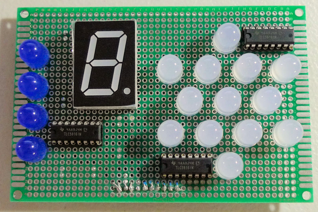
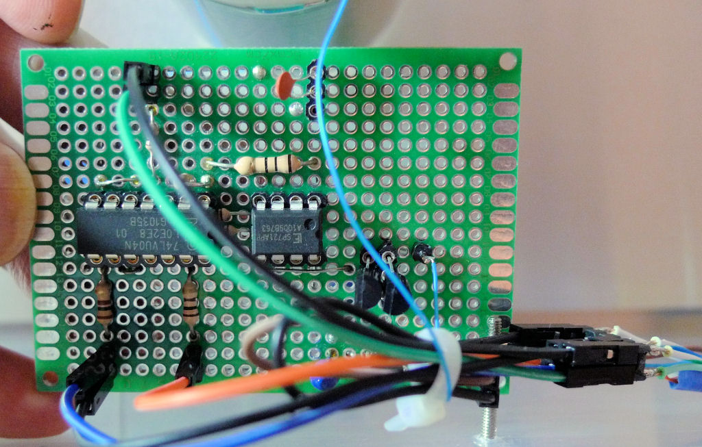
The front of the board.  The ICs and silver pads are quite visible here which is kind of unfortunate.  It would be nice to have a purely black background for the LEDs to increase the contrast.


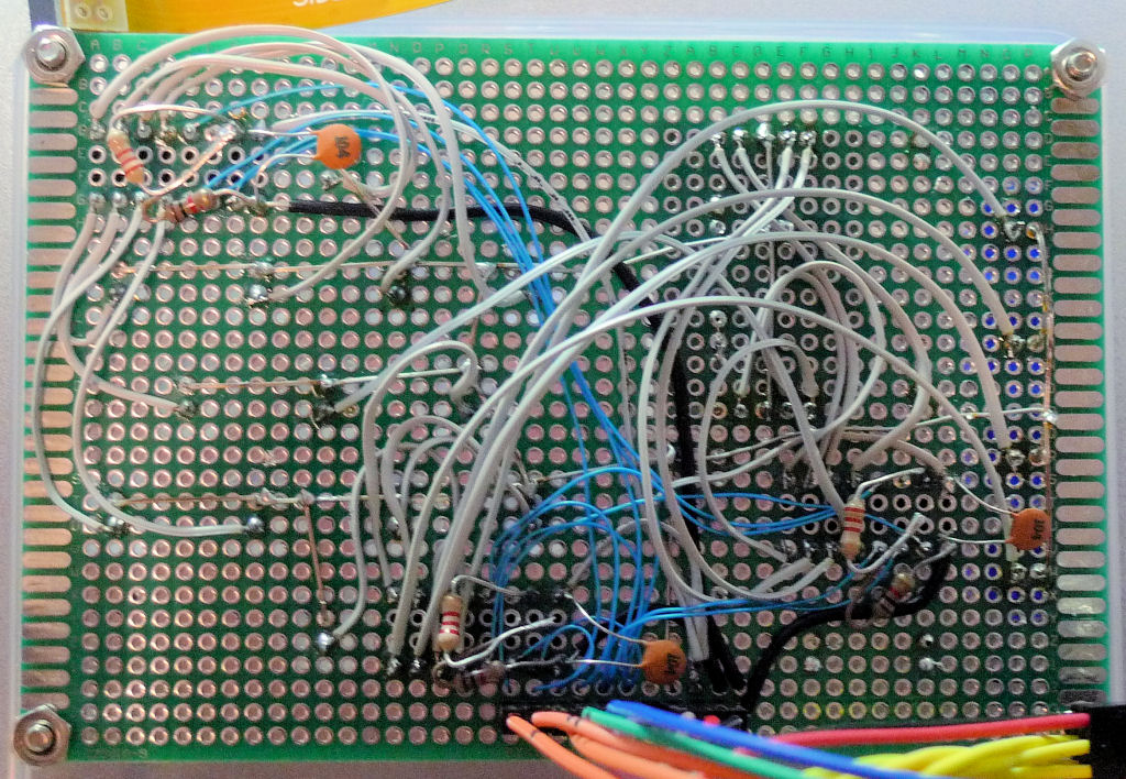
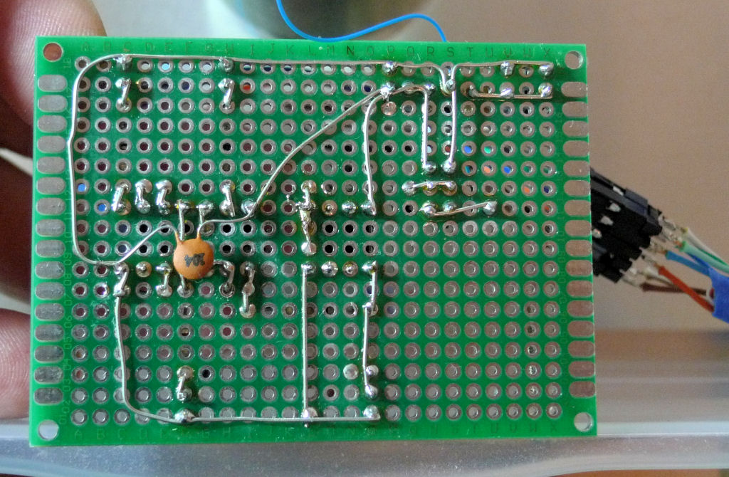
The back of the board is a rat's nest of wires, but that's about it.  The reason you see 6 resistors here is I used 2.2k + 1k in series (was adjusting the current and never replaced the two with a single 3.3k).


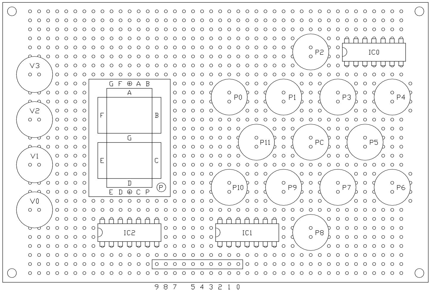
Here's a precision view of the board as I would probably lay it out now.  I only put the octave display higher on mine because I didn't feel like moving IC2.


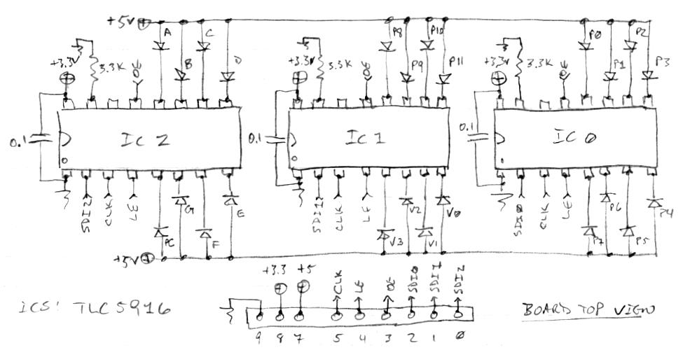
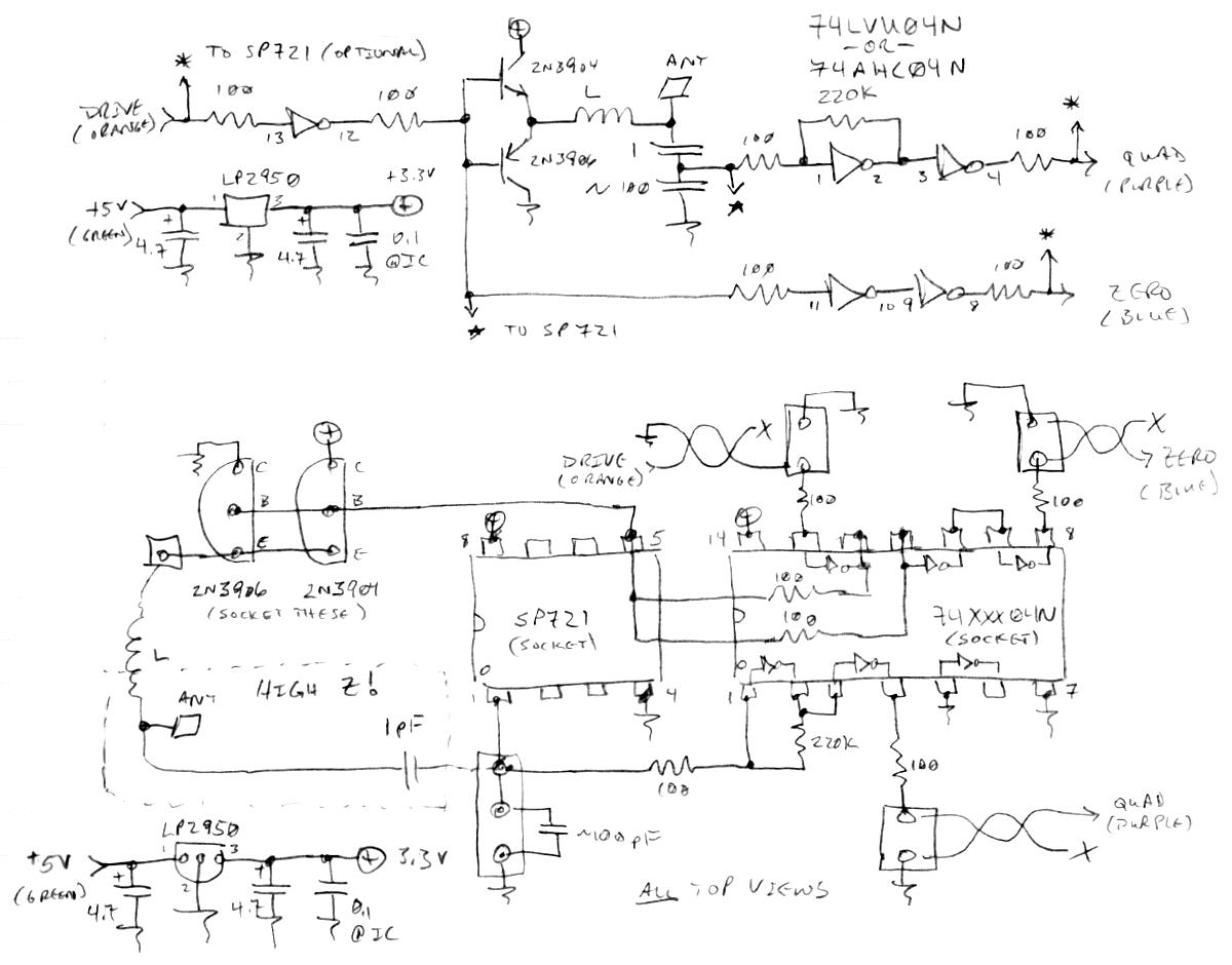
The schematic.  I would swap SD0 and SD2 at the connector just to keep things clearer at hookup.  FPGA pins can always be easily relocated too.

Honestly, I rarely consult the octave display, so it could probably be a lot smaller.  It would be an interesting experiment to see how small the note display LEDs and star pattern could be made and still have it as readable and effective as the 10mm here.

The volume display is more useful than I thought it would be, giving visual feedback on things like knee point setting and the like.

What's really nice about the note display is, after you use it for a while, when you're picking out melodies by ear you can easily "see" what the key of the song is just by the pattern the notes take.  It's sort of like playing the guitar, where it's more about the relative patterns the notes make on the fretboard than it is about the specific notes themselves.  And the tuner UI page has a note offset knob, so you can play anything in the key of C tuner-wise until you get used to the other patterns - there are obviously 2 and their rotations.

I haven't used pitch preview and I'm thinking I probably never will.  Even when I could clearly hear what my EW was doing pitch-wise, I'd always wander off into the weeds when playing unaccompanied.  That literally never happens to me now with the tuner.  Pitch correction helps too, but I'd say 90% of it is the precise pitch feedback the tuner provides.  Without the tuner I probably would have given up on the hope of playing with any level of precision by now.  And my ear isn't all that bad (after decades of tuning my guitar and singing).  People without a really good pitch sense must spend a fair amount of time more or less lost on a conventional Theremin.

And I say the above not to piss anyone off, nor to make them feel bad about their Theremin, nor to blow my own horn.  I frankly am a bit shocked at how much the note display improves playability, but people are different and so YYMV here as in all things.

You must be logged in to post a reply. Please log in or register for a new account.