The Hardwareing: Fashion Shots
Some more pix of the outsides and insides. The boxes are mounted on sleazy CCTV camera mounts (use something else! like the most excellent though somewhat pricey RAM ball mounts I have in the parts list) that barely keep things in position without torquing down on the cheesy plastic thumbscrews so hard it feels like they're going to snap off. The wooden stick base is a 3/4" thick x 3" wide x 900mm long piece of scrap plywood I scrounged from the garage. The control box and the microphone mount underneath are located in the center of the 900mm length, the antenna mounts at either end. I've got the volume antenna box mount on the bottom of the plywood, you could probably mount it on the top instead if whatever you're using for mounts articulates sufficiently.
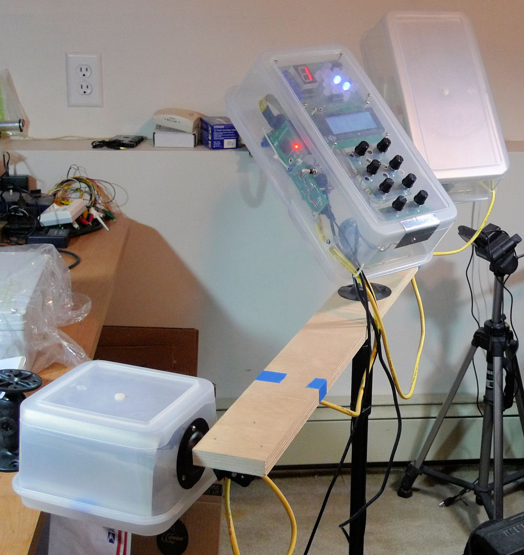
Make love to the camera baby! (Please pardon my messy lab and work area, I'm a bit of a pig.)
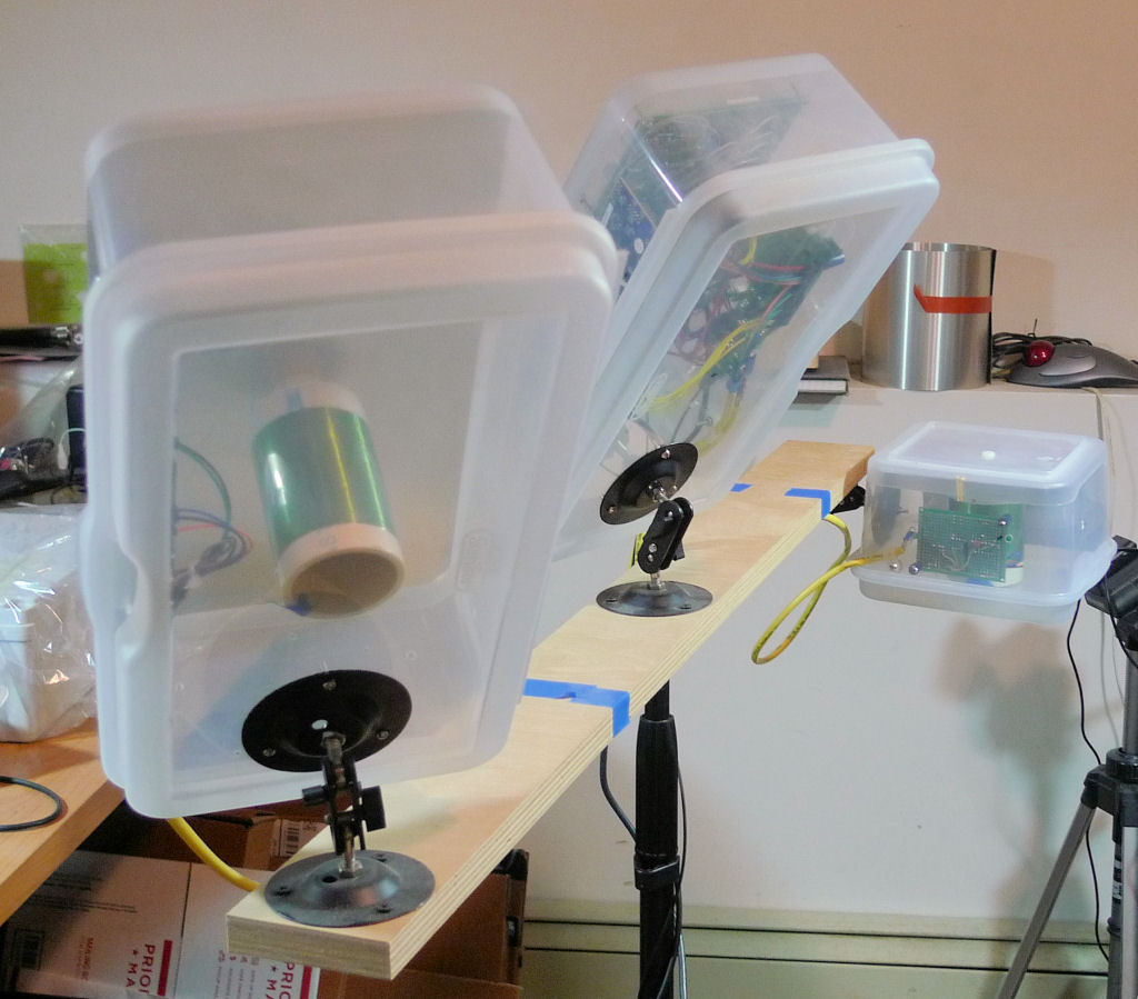
A better view of the mounts (and the sty).
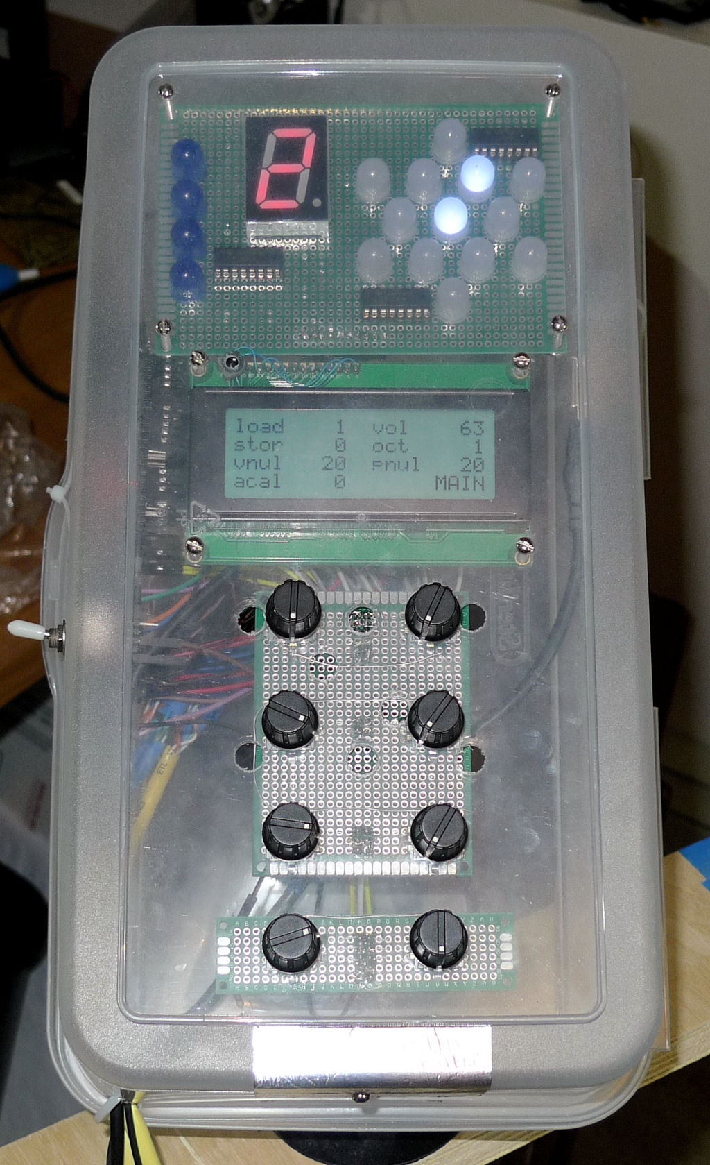
The control panel. LED tuner a the top, LCD display at the center, rotary encoders below that, ESD pad along the bottom edge.
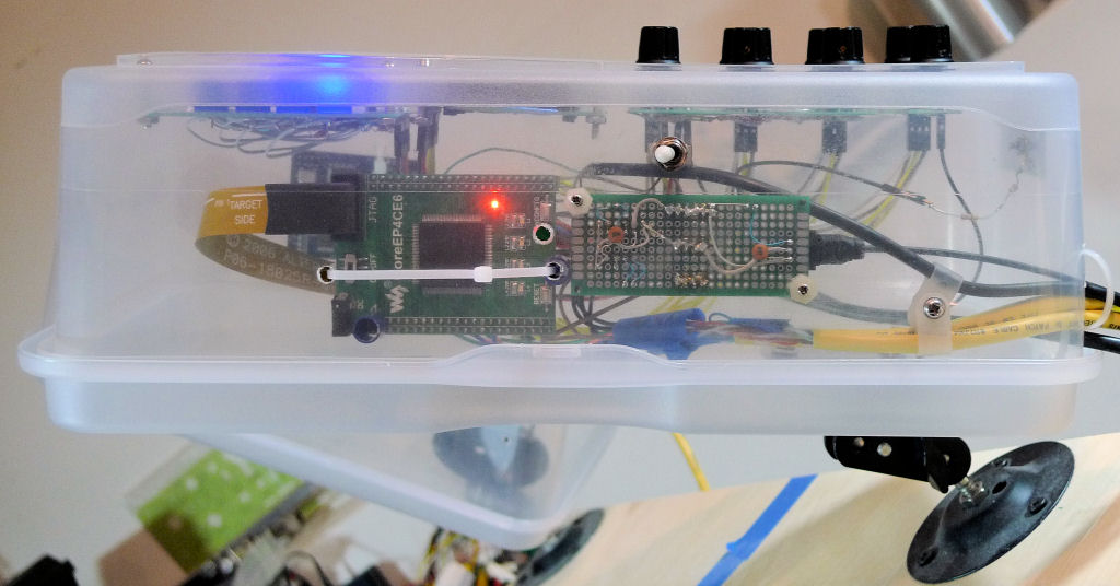
The left side. That's the FPGA board to the left, the SPI EEPROM / TOSLINK TX / power distribution board to the right, and a small toggle switch above it for power. Note that the Altera USB-Blaster ribbon is unfortunately rather captive here.
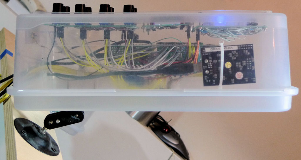
The right side. That's my Altera USB Blaster to the right, sans it's plastic enclosure give the zip tie something to grip, but mainly to give access to the programming ribbon cable so as to avoid power cycle catastrophes. If you aren't doing a lot of FPGA development then you probably don't need to co-locate the programmer with the FPGA board, but do somehow provide easy access to the programmer pins on the FPGA board, perhaps via a header extension or ribbon cable or similar. You might want to buy a second USB extension cable for the programmer if you end up using it a lot.
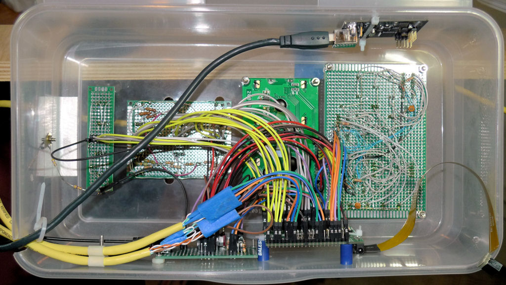
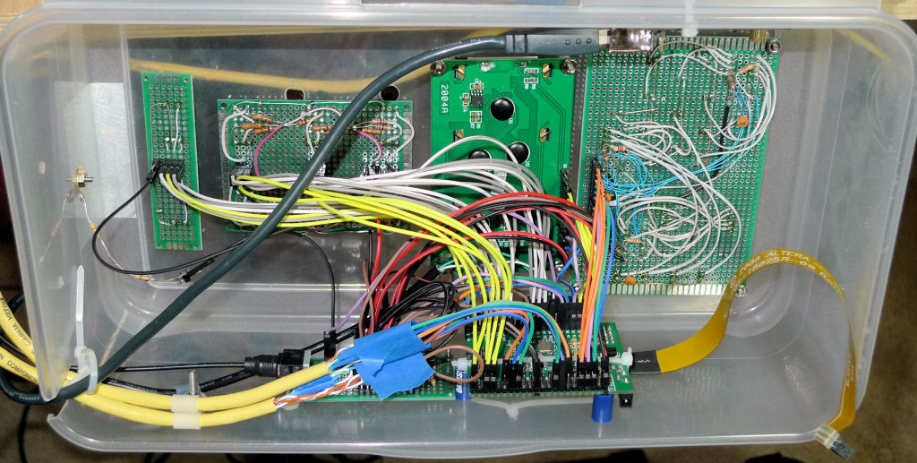
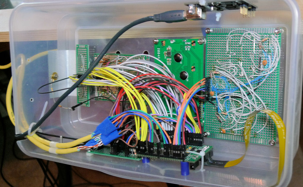
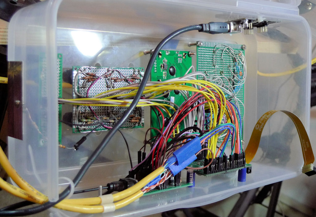
Some different angled views of the inside of the control box. Spacers are nylon nuts or ballpoint pen case cut down. Stuff held in place with screws & nuts / zip ties. If you look closely you'll see that the 2 x 3 encoder board has discrete pullup resistors (10k IIRC) and the 2 x 1 doesn't. There are programmable pullups inside the FPGA so no external resistors are necessary, and there just isn't any reason to remove them at this point.
You can also see the back of the LCD panel here, the small IC and passives just to the right of "2004A" comprise the 3.3V => 5V level shifter. If they're not there then EastRising sold you the wrong (3.3V logic / 5V LCD) part.

