Digital Theremin LC Tank Q Limitations
Some basic background, experience, and conjecture on this.
R, L, C:
1. Resistors (R) convert electrical energy to heat, which leaves the circuit, never to be seen again. (Oddly, they also spontaneously generate noise which can be quite troublesome in analog electronics - the R's in your junk box are hissing at you right now!)
2. Inductors (L, measured in Henrys) and capacitors (C, measured in Farads) are energy storage devices. They can and do have varying types and degrees of energy eating parasitics, but ideally they act as reservoirs for energy, using a magnetic field (L) or electric field (C) as the storage medium. Ideally all of the energy that comes in is available to go out.
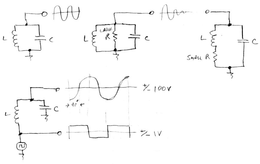
3. L's are coils of wire, and wire has resistance, so the longer and thinner the wire the higher the resistance of the L - this is known as direct current resistance (DCR) and you can measure it with the ohms setting on your DMM. DCR behaves exactly like that measured R in SERIES with a perfect L.
4. C's almost always behave more ideally than L's, that is, they are characterized less by their non-ideal parasitics and more by their energy storage capacity. Unlike L's, C's aren't plagued by magnetic field interference, and many useful C values can be made physically quite small. For these reasons you see lots of C's in modern circuitry and almost no L's.
LC tank, Q:
5. Functionally, L's and C's are opposites of each other. L's are short term opens and long term shorts, C's are short term shorts and long term opens. Bizarrely, if you hook an L & C in parallel (an LC "tank") and either has any energy stored, that energy will transfer back and forth between the two - sinewave oscillating / ringing ideally forever, only decaying due to parasitic and other energy losses.
6. This decaying is known as damping, the value of which is the fraction of total energy lost per cycle. Q, or quality factor, is the inverse of damping. So infinite Q = zero damping = no losses = ringing forever.
7. The resonant frequency of the sinewave oscillation of a ringing LC tank is given by 1 / [2*pi*sqrt(L*C)].
8. Just like pushing a child on a swing, small electrical pushes applied to high Q LC at the resonance frequency can result in quite large voltage oscillations across the L & C. The final amplitude is limited only by the energy losses!
9. Q directly multiplies the tank drive amplitude. Give an LC tank with Q=100 a drive of 1V and it will swing 100V. This is great for drowning out environmental interferers and intrinsic oscillator noise.
10. Q is measure of discrimination, so you want high Q to better pinpoint resonance frequency and swamp (by effectively putting a big flywheel on) interference. In some instances you may want to lower Q in order to smear out resonance and operate over a larger range off of the resonance point (this is how the volume side on the Etherwave and others works).
11. Adding some R to the LC tank lowers Q / smears out the resonance. Either a large R in parallel with the LC, or a small R in series with the series L drive (see #13).
12. L DCR acts like a resistor in series with the series L drive!

LC oscillator drive:
13. The most direct way to drive an LC tank with low voltage modern digital logic is to break one LC connection and insert a grounded low impedance drive. This grounds the C and wiggles the L. When the drive signal is at LC resonance, the unbroken LC node will swing with a large amplitude sine wave, even if the drive is a square wave, because the LC is acting like a second order lowpass filter, hugely suppressing all harmonics of the drive waveform. At resonance the high voltage swing node will lag the drive signal by exactly 90 degrees ("quadrature"). For example, the prototype uses a ~2V p-p tank drive, and the ~100 Q tank air core solenoid L and plate antenna C cause the antenna to swing ~200V p-p.
14. An LC tank can be driven somewhat off of its natural resonance frequency and still give largish, though reduced, amplitude swings.
15. Higher Q means less room for error with phase of the drive signal.
16. It may not be obvious at first glance, but simple analog LC oscillators often depend on phase error in order to work, and may introduce losses in order to sense / time the tank drive.
17. Phase drive error leads directly to off resonance frequency error, and thus LC tank voltage swing reduction. If you're simulating an LC oscillator with perfect LC and the tank swing isn't huge, there is too much drive phase error (you're off resonance) and/or there are circuit elements wasting energy.
18. Phase locked loop (PLL) LC stimulation techniques can enforce exact quadrature between series L drive and antenna C, therefore maintaining oscillation at the exact LC resonance point, therefore maximizing tank / antenna voltage swing.
19. Phase gain is Q/pi, and this is important because it is part of the PLL loop gain, so it must be accounted for (loop gain < 1 for stability, loop gain determines loop bandwidth). You can directly see high phase gain on a scope by observing both the drive and antenna signals with variable frequency drive - the relative phase of a high Q tank will suddenly "pop" from 0 degrees to 180 degrees when transitioning through the resonance point unless you're adjusting the drive frequency quite slowly. At quadrature the "pop" rate is at its peak.
Theremin losses:
20. The "antenna" of a Theremin functions mostly like one "plate" of a capacitor, with the air around it the dielectric field, and anything conductive past that the other "plate" of the capacitor.
21. Human body interaction with a Theremin antenna is very much like a variable capacitor, with the human side "plate" grounded through a series R. The closer the human hand or other body part to the antenna, the higher the mutual C, but the losses increase as well due to the body R. You can readily demonstrate this by placing a scope probe near the Theremin antenna and watching the amplitude on the screen become dramatically reduced as the hand approaches.
22. The "skin effect" starts kicking in at fairly low frequencies, magnifying DCR. The moving charges in the L wire flee from the center of the wire and crowd to the outer edges or skin, causing an effective reduction in the cross sectional area of the wire, raising the AC resistance, and lowering Q. (My solenoid spreadsheet calculator takes this into account.)
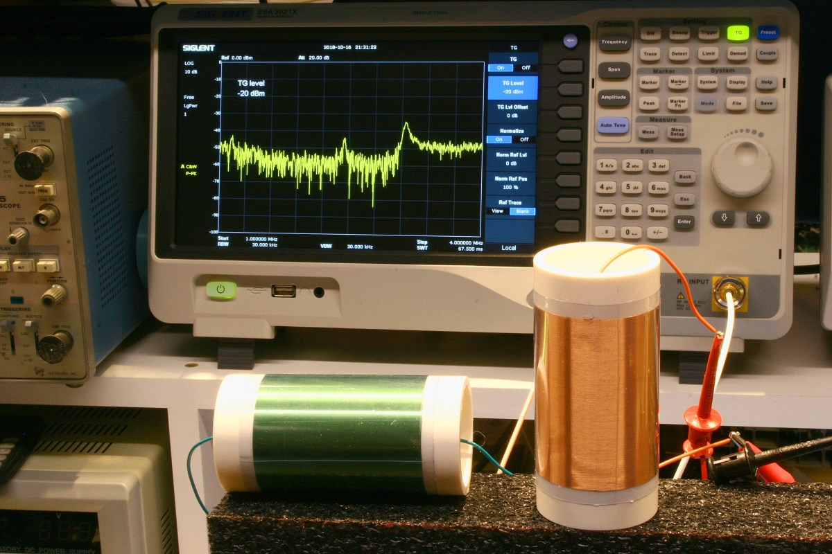
23. There are RF losses as well, and I believe it is these that ultimately place an upper limit on LC tank Q.
When I first started winding coils I reasoned that the L DCR would be the overwhelming LC tank Q determinant, so I tended towards larger diameter wire which required physically large coils. But the huge Q's never materialized, and coils wound with thinner wire behaved about the same. It's obvious that a Theremin "antenna" actually behaves like a very short, highly resonant, coil loaded dipole with capacitive cap. And I believe the way those work is to jack up the antenna voltage swing via LC resonance, and thus somewhat make up for their huge impedance mismatch to the "ether" via sheer amplitude. Sort of like screaming to be heard because someone has their hand clamped over your mouth.
Anyway, it doesn't take much in the way of drive phase error or R or RF losses to seriously lower a high Q swing, it's a fairly tenuous thing. The most you can hope for here is maybe 200 or so, and that's really pushing it. Lucky for us, 100 or even less seems to work fine, though I worry about the RF disturbing transmissions and such.
[EDIT] The shorter the antenna the less well it behaves as an antenna, so the lower the RF transmission. So a circular antenna fed from the middle is something of a best-case here in terms of highest C interaction with the hand and smallest physical dimension to radiate RF? I'm strongly thinking that my next build will have circular center-fed antenna plates, perhaps with some kind of bulls-eye painted on or a contrasting outer rim, to see them better peripherally.


