CIC (huh, good god y'all)- what are they good for? (absolutely nothing)
Well, CIC (cascade of integrators and combs) are pretty great for some things but I just tore all four of them out of D-Lev code. I know I went on and on about them in the past, but I've got more DSP under my belt now and can see them for what they are.
I was using a second order CIC, half in hardware (cleverly part of the NCO phase accumulator) and half in software, to change the sample rate of the LC DPLL frequency point from 196.666MHz to 48kHz. As sample rate changers go they're not the best until you get to 3rd order or higher (I was using 2nd order) which means really wide accumulation, which is too slow to run at the SPDIF master clock rate of 196.666MHz. I swapped them out with a cascade of three 1st order "fast" IIR low pass filters, which just barely meet timing (but do), and provide >80dB of anti-aliasing at PCM Nyquist of 24kHz with a cumulative -3dB point of 480Hz. Here's a spreadsheet on the fast IIR:
http://www.mediafire.com/file/18gj2oyw28f21ag/fast_iir_2012-12-20.xls/file
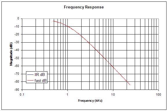
The above is the frequency response of the "fast" IIR cascade implemented in the D-Lev.
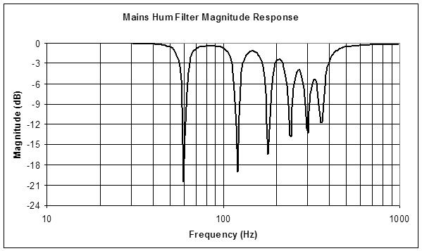
CICs also formed the mains hum filters for both axes, where they worked well but gave a 1st order roll-off around 30Hz, they gobbled up a ton of my precious RAM, and the notches were rather broader than I would have liked. For a while I bookended them between two 150Hz 4th order low pass filters and ran the CIC hum filters at 1/16 the rate to save memory, but upon testing them in-depth yesterday I couldn't seem to reproduce the hum suppression results. So this morning I looked into notch filters, and it turns out that you can make a really great notch filter from a Chamberlin state variable by summing the high and low pass outputs. The resulting output is quite interesting in that the peaking associated with higher Q values disappears, as does the high pass amplitude deviation from 0dB, and we're left with a variable width notch that can go from fairly broad to surgically narrow. Here's a spreadsheet on the Chamberlin notch:
http://www.mediafire.com/file/8qtd4dj7tvs60aj/notch_2018-12-25.xls/file
The notch algorithm is pretty efficient, with the subroutine consuming a mere 13 cycles. So the hum filter is now a cascade of six notch filters with a 4th order low pass to smash the rest of the higher harmonics. For 60Hz the notch frequencies are 60, 120, 180, 240, 300, and 360Hz; for 50Hz they start at 50Hz and increment by 50. The 4th order low pass in both cases is set to 300Hz. I'm using a table in software to select between the two sets of notch frequencies, and the damping I chose is a constant 0.5 for all.
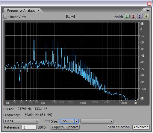
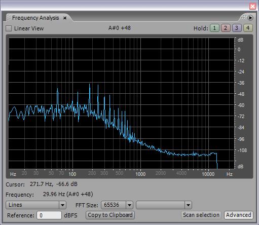
Subjectively the axes perhaps seem a bit less noisy when operating in the far field, it's hard to tell. Low frequency noise should be rather low anyway as it is small signal grounded through the tank coil and drive (I've never heard the prototype pick up any kind of hum whatsoever). There is a definite massive reduction in the amplitude of the noise on the operating point numbers, though you would see that happening with almost any kind of filtering. 60Hz and its harmonics are clearly suppressed, and switching to 50Hz in my lab setting causes them all to jump up considerably, so I'm certain that it's working as designed.
Just when you think you've scienced the shit out of something, it ends up needing more. Ah well, it's on a firmer theoretical footing now, and there should be more in the way of clean gestural bandwidth available.
I also implemented a rudimentary pitch preview system but it may need refinements.
This project is kind of like doing a crossword puzzle. Very slow at first, then as things start falling into place it goes faster and faster until you hit the hell-for-leather final phase where it seems everything gets wrapped up at once.
Happy Holidays y'all!


