All About That Bass (no and Treble)
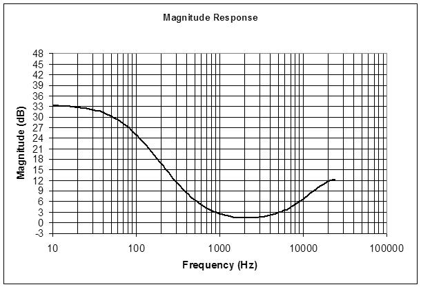
Added bass and treble tone controls to the D-Lev prototype yesterday. Implementing the loudness control (an unexpected bust in terms of use) prepared me for it. I had a spreadsheet sim from around then which I updated and played with until I was satisfied with the results [LINK]. Here's how I did it:
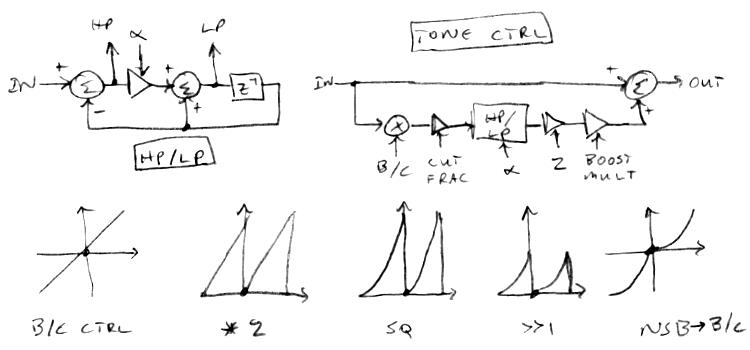
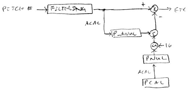
At the upper left is a HP (high-pass) and LP (low-pass) filter which we add / subtract from the input to form the tone control at the upper right. At bottom is a method to linearize the boost/cut encoder.
For the filters we use the standard first order type, with no delay on the low pass output (in order to make the larger construct feed-forward). We employ a low pass filter for the bass control and a high pass filter for the treble control. We cascade a bass and a treble unit to get both controls.
The transfer function of a first order low pass filter is:
out / in = alpha / (1 + z^-1(alpha - 1))
The transfer function of a first order high pass filter is:
out / in = (1 - z^-1) / (1 + z^-1(alpha - 1))
where alpha is:
alpha = 1-e^(-2 * pi * Fc / Fs)
Conversely, if given alpha then the cutoff frequency is:
Fc = -ln(1 - alpha) * Fs / pi
Boost / cut is accomplished by multiplying the filter input with the signed boost / cut control value, multiplying this by the cut fraction, selecting the boost / cut filter frequency, doing the filtering, multiplying the result by the boost multiplier (only if boosting), then summing the result with the input value - which is a surprisingly involved process!
It's not obvious, but you need to use separate filter frequencies for boost and cut. For the bass control, the cut filter frequency should be approximately 2x the boost filter frequency. For the treble control, the boost filter frequency should be approximately 2x the cut filter frequency.
The cut fraction subtracted from one should roughly reflect the maximum cut ratio (e.g. 0.9 for -20dB). The boost amplitude multiplier (multiplied by the cut fraction) should roughly reflect the maximum boost ratio (e.g. 10/0.9 = 11.1 for +20dB), though all things DSP tend to deviate, particularly at higher frequencies.
Since the filters are only first order, there is some interaction going on in the midrange. A good question here is: what is the center of "midrange"? My ears and brain tell me this is somewhere around 500Hz or so when listening to a variable tone source. The geometric mean of 20Hz and 20kHz is 632Hz. Another good question is: how much boost / cut is necessary? +/- 15dB sounds sufficient to my ears, and this keeps midrange gain variation fairly reasonable.
To minimize overload, the control and cut fraction multiplications are placed before the filter where they form an attenuator. Signed control here is usually in the range [-0.5:0.5) which knocks the amplitude down by at least 1/2, which, along with the application of the cut fraction, gives sufficient headroom for the high pass calculation inside the filter. Obviously, the output of the filter output must then be multiplied by 2 to compensate.
Scaling of the boost / cut control is a critical element of the design. Going from cut to boost involves an large gain differential (boost gain), which could be especially obvious around zero. And the general spacing of the control detents is quite non-linear. If we multiply the signed control value by 2 modulo to give dual unsigned ramps, square this, divide it by 2, and then translate the negative side ramp down by flipping the MSb, we end up with a construct that linearizes the control pretty well over the full range.
For various boost and cut values, the curves are not symmetric about the 0dB axis. Fixing this involves scaling the cut mode cutoff frequency with some function of the cut strength. I chose not to fix this, as first order filters are pretty indistinct sounding in the first place. The ear really can't discern whether or not it's hearing scientifically accurate first order filter shelving.
Anyway, here it is the simulation boosting the bass and treble by ~9dB:
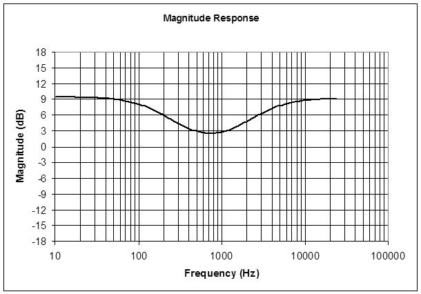
You can see some raising of the midrange here where the bass and treble boosting overlaps, with the center of the dip somewhere around 700Hz.
Implementing mathematically perfect (literally textbook - see Zolzer's treatment) bass and treble controls involves dynamically solving a LOG and a ratio of TANs (though the TANs could be pre-computed if not varying the cutoff frequency), which is way more trouble than the results are worth IMO. If one were building a mixing console, or a multi-band equalizer, then the computational effort would be easier to justify.
Here's a sample of it in action: [MP3]. First the bass is cut then returned quickly to zero, then it is boosted and returned quickly to zero, then the same is done for the treble control. The test signal is white noise, which I probably should have cut down on the high end some as it swamps the low end.


