Let's Design and Build a (mostly) Digital Theremin!

Posted: 10/29/2022 5:17:46 PM
dewster

From: Northern NJ, USA

Joined: 2/17/2012

Trumpet sounds nice.Halloween D-Lev mix is awesome!

Thanks!  Though I heard a muted trumpet on a CD yesterday that sounded less tinny and more pleasant.  Need to figure it out...

P.S: Found EP4CE22 board with interesting form factor on aliexpress. Linear regulators. But this is noname chinese manufacturer (unlike QMTECH which is almost brand).

Oooh, thanks!  That pretty much checks all the boxes, thought the pinout spacing is kinda tight at 1.27mm.  There doesn't seem to be a 3.3V regulator on the board?  So they're either punting to an external supply provided by the user (a good move actually, as better heat sinking can be provided) or all the I/O is 2.5V, which may be a deal killer.

Posted: 10/29/2022 9:20:41 PM
Buggins

From: Porto, Portugal

Joined: 3/16/2017


Oooh, thanks!  That pretty much checks all the boxes, thought the pinout spacing is kinda tight at 1.27mm.  There doesn't seem to be a 3.3V regulator on the board?  So they're either punting to an external supply provided by the user (a good move actually, as better heat sinking can be provided) or all the I/O is 2.5V, which may be a deal killer.

I wonder if it is possible to contact to seller and ask for schematics?
For several boards I purchased on aliexpress, any documentation can be seen only after you paid for order

Posted: 10/31/2022 12:48:00 PM
dewster

From: Northern NJ, USA

Joined: 2/17/2012

Basic Issues

I've been pondering some basic issues lately.

Body Intrinsic C
We've all seen Theremins behave poorly when not properly grounded, and we've all seen Theremin pitch jump when e.g. we touch something metal with our bare foot, but how much does the body actually need to be AC grounded / coupled back to the Theremin?  It seems that the intrinsic C of the body is sufficiently large that it acts as a ground for the small mutual C formed by the hand & antenna.  As a thought experiment here, Theremins usually work OK on the second floor of a wood house, with the player wearing insulating shoes.

Antenna / Hand Impedance
What is the importance of the impedance of the antenna coupled to the impedance of the player's hand?  Instinctively one might think that the higher the impedance the better, as this would seem to relieve current return path demands, which are largely uncontrollable.  An LC node at resonance has infinite impedance (only limited by parasitics, i.e. Q) which seems ideal.  But with relatively large AC voltage swings (>100 Vpp) relatively large AC currents (>10mA) are whipping back and forth through that LC node, which would seem to require a low impedance return path to function.

LC Oscillators
High Q LC oscillators are so attractive from so many angles.  The LC naturally oscillates, so it only requires little periodic pushes to keep it oscillating, which can be done with very little gain (low additional noise) and very little energy (low heat) - increasing short-term and long-term stability.  Q voltage multiplication means the oscillator can be powered from a very low voltage source yet still develop a high antenna voltage swing - swamping most environmental interference.  When well designed, the oscillation is essentially sinusoidal with very low power harmonics, so unintentional emissions don't seem to be a problem for compliance. 

But the delicate nature of the high impedance at resonance means external interference like mains hum easily gets in, though this can be combated digitally.  Just the presence of even unpowered similarly tuned LC circuits nearby can be a coupling problem though.

The body impedance contains a resistance which tends to damp oscillation as the hand approaches, but this isn't such a bad thing, as excessive resolution isn't needed in the near field, and oscillation amplitude in the far field isn't affected as much.

Because the LC naturally oscillates, the drive circuit only requires a single threshold to work.

High Q coils require precise drive in order to supply maximum voltage.  Except for PLL approaches, all LC oscillators have phase error issues, which understandably are more of a problem when operating at higher frequencies.  Higher frequency operation is desirable because air core coil size shrinks roughly with the square of frequency (all other things being equal).

Inductors are notoriously bulky, difficult to source, non-variable, and can pick up magnetic interference as well.

RC Oscillators
If high impedance is desirable, are RC Theremins inferior in this regard?  Or do they generally present sufficiently high R to the hand C?  Large R is a noise source.

If there is only one each of the L, R, C elements, then RC operating point is proportional to C, whereas LC resonance is proportional to the square root of C.  This means an RC oscillator will be twice as sensitive as an LC oscillator for small changes in C.

RC oscillators usually require two high gain thresholds to function, which add noise and therefore instability, and the power per cycle is lost as heat.  They are fundamentally less stable than an LC because of these issues, but can the increase in sensitivity make up for this?

RC oscillators that contain a single C are not sinusoidal.  The harmonics have significant energy, so radiated emissions could be a compliance problem.

RC oscillators can be tuned by changing R, which is much easier than changing the L of an LC oscillator.  They can also be modulated to spread the spectrum, which can help combat environemntal interference / aid in passing compliance / allow multiple sensors to co-exist.

RC oscillators have no L! 

RC oscillator could have a strong digital component in its construction, rather like DPLL.

Antenna Shielding
Could effectively almost double sensitivity by "disappearing" one side of the antenna intrinsic C.

Could perhaps reduce unwanted local interaction (nearby band members, audience, etc.)

Obviously would work better with plate antennas, as they are significantly 2D in area.  This would be a reason for plates on a digital Theremin beyond their near-field linearity and playability advantages.

Shield drive would require a high voltage DC source and high voltage buffer if the antenna voltage swing is wide, but shielding may reduce the need for high antenna voltage swing, thus making it easier to implement. 

A high voltage shield would probably require insulation as it is low impedance and more of a shock hazzard.

Shield drive buffer input could significantly load the antenna (though something has to detect thresholds anyway, particularly for RC).

Shield drive could induce oscillation.

Future Testing
RC oscillator with a shielded plate antenna, perhaps with spreading.  Measure stability and sensitivity.

Posted: 10/31/2022 9:24:09 PM
Buggins

From: Porto, Portugal

Joined: 3/16/2017

Eric, are you looking for possible RC sensor solution?

If there is only one each of the L, R, C elements, then RC operating point is proportional to C, whereas LC resonance is proportional to the square root of C.  This means an RC oscillator will be twice as sensitive as an LC oscillator for small changes in C.

I was very surprised when tried to compare sensitivity of RC and 1/SQRT(LC).
It's non-intuitive that y=x is ony twice sensitive than y=sqrt(x). Unless you try to compare them on limited range of C change.


RC oscillators that contain a single C are not sinusoidal.  The harmonics have significant energy, so radiated emissions could be a compliance problem.

We can drive RC with non-square signal to reduce harmonics.
Triangle wave has less harmonics, and easy to generate in analog cirquit.
Sine has minimum harmonics, but hard to achieve. Good lowpass filter on square or triangle source signal may help.

I have an idea how to reduce noice level.
Let's drive RC with low voltage signal. E.g. we have 3.3Vpp on antenna of RC theremin, instead of usual 30-300Vpp on classic LC.
So, noise signal received by antenna will be 10 to 100 times more noisy.
Usual methods to measure phase shift or frequency of signal use only zero crossing point.
If it's possible to take into account whole signal period instead of only 2 points, may allow to filter out a lot of noise.
One example of such solution is correlation between two signals. But it requires a lot of computations and cannot be done in analog.
Another solution: add two signals and measure amplitude of result - it will depend on phase difference, and noise will be filtered out by averaging.
I believe there may be some simple way to utilize information from the whole waveform of signal, not only peaks or z-crossing.

E.g. in analog theremin mixer, whole period of variable oscillator is being used when we mix it with fixed frequency using analog multiplier.

Antenna Shielding

Eric, could you please explain what is antenna shielding?
I could not catch it at all.

Posted: 11/1/2022 7:32:23 PM
ILYA

From: Theremin Motherland

Joined: 11/13/2005


"what is antenna shielding?"


Is it?

http://www.thereminworld.com/forums/T/29205?post=203060#203060

Posted: 11/1/2022 8:56:28 PM
dewster

From: Northern NJ, USA

Joined: 2/17/2012

"It's non-intuitive that y=x is ony twice sensitive than y=sqrt(x). Unless you try to compare them on limited range of C change."  - Buggins

That surprised me too, had to spreadsheet it to make really sure, though there are a lot of functions that look pretty similar over limited ranges.

"We can drive RC with non-square signal to reduce harmonics."

I think the RC (or IC: current source and C) pretty much have to create the waveform themselves?  Which gives a "sharkfin" type wave for RC, and a triangle wave for IC.

"Usual methods to measure phase shift or frequency of signal use only zero crossing point.  If it's possible to take into account whole signal period instead of only 2 points, may allow to filter out a lot of noise.  One example of such solution is correlation between two signals. But it requires a lot of computations and cannot be done in analog."

Yes, this is something that's bothered me for a while, not correlating the entire waveform seems like a lost opportunity for increased resolution and noise reduction.

"Another solution: add two signals and measure amplitude of result - it will depend on phase difference, and noise will be filtered out by averaging.
I believe there may be some simple way to utilize information from the whole waveform of signal, not only peaks or z-crossing."

AM solutions seem prone to noise?  Resolving in the time domain with a crystal reference you can get really high res data, resolving in the amplitude domain you're really limited to AD precision, system noise, etc.

"E.g. in analog theremin mixer, whole period of variable oscillator is being used when we mix it with fixed frequency using analog multiplier."

True.  Mixing down to baseband audio invites latency and noise due to long period measurement and lack of averaging, but mixing down to an intermediate could help (this was my plan long ago because it can also linearize if the planets are aligned).

"Eric, could you please explain what is antenna shielding?"

As ILYA points out above (though FredM's example is overly complex because he was thinking of using it as a linearization scheme) it's using one plate of a sandwich of 2 as the antenna, and driving the other plate with a 1:1 buffer with the antenna signal.  The antenna plate would then have ~1/2 of the intrinsic C, and the mutual C would be somewhat directional, at least in the near field.  Mutual C delta should increase because there would be fewer lines of force transferring from the hand to space and back with hand movement.  So we get directionality and a sensitivity boost, and could probably employ a lower plate voltage swing.  Buffer input parasitic C might eat some of that up though.  Any variation in buffer gain could be a problem, and gain over 1:1 could oscillate.

I haven't ever encountered a Burns Theremin, but the fact that they work at all is encouraging.

I've seen driven cable shielding used for PH meters, and also charge balanced oscillators used there.  This is where the capacitor is discharged with a constant current source, and once it reaches some threshold you push a known slug of current into it via another constant current source applied for a constant time.  It's sort of asymmetrical dual slope integration.  By modulating the charge time you could shake up the emissions, and a coordinated effort here might allow sensors to be placed near to each other.  A boy can dream!

[EDIT] Just saw active shielding used with EEG electrodes, which makes sense as the signals are in the microvolt region.  One might actually shield not just the back plate, but a coaxial cable feeding the antenna plate, with the shield buffer and oscillator located back on the main board.  Though the cable C might be overly temperature dependent?

Posted: 11/3/2022 7:00:16 PM
Buggins

From: Porto, Portugal

Joined: 3/16/2017


As ILYA points out above (though FredM's example is overly complex because he was thinking of using it as a linearization scheme) it's using one plate of a sandwich of 2 as the antenna, and driving the other plate with a 1:1 buffer with the antenna signal.


Interesting. A bit similar to on-screen capacitive sensor tuned to sense bigger distances.
Unlike screen sensors, pieces of pattern on each surface can be connected to single point.
BTW, probably it's possible to split antenna into regions (e.g. 3x3) to have 3d sensing of hand position.

Can such antenna be built just as FR4 PCB with patterns on both sides (or fully populated back side and pattern on front side).

Is there any difference in sensitivity and noise level between following cases:
- back surface is drive, front surface is sensing
- back surface is GND, front surface is drive+sense

Back surface can be pattern not overlapping with front surface to reduce mutual capacitance between surfaces and increase surface1-hand-surface2 capacitance sensitivity (but with reduced shielding).

Does someone know any method to calculate C of caps with complex shape and position electrodes?
Is there any method to do such calculation?
E.g. if there is some formula for two small flat electrodes with big distance between them, and non-parallel orientation, can we apply it to pairs of small pieces for both electrodes, and summarize / integrate to get resulting capcaitance?
If we can write some program to do such calculation, we can try to find optimal configuration of shielded antenna layers.

Maybe some unusual electrode pattern, similar to Fresnel zone plate may make antenna highly directional?

Posted: 11/4/2022 5:17:57 PM
dewster

From: Northern NJ, USA

Joined: 2/17/2012

Vox In The Box

Katica very kindly sent me audio samples of two Claravox voices she particularly likes.  These are modern mode voices, not traditional, so I presume they are synthesized in the first place.

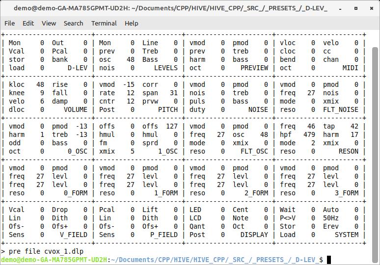
The first voice is nice and fluty sounding.  Spectral analysis shows prominent first and second harmonics, with very little other harmonic content.  The way to implement this on the D-Lev synth is to offset the second and third oscillators by one octave and xmix them with the first oscillator, then introduce a tiny bit of upper harmonics with harm[1]:

I was surprised that the other harmonics were even audible, being more than 50dB down.

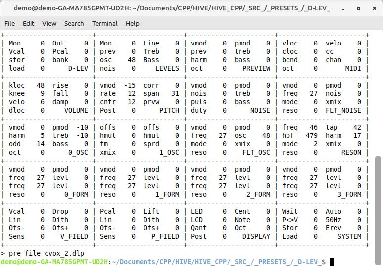
The second voice is simpler and vaguely feminine sounding in the upper registers.  Spectral analysis shows the second and third harmonics roughly 30dB down from the fundamental but the same level as each other, and the fourth and fifth further down and again roughly the same level as each other.  The way to implement this on the D-Lev synth is to somewhat emphasize the odd harmonics with odd[14]:

I gave both a bit of negative pmod to increase harmonic content for lower pitches, and rolled off the highs a bit with some negative treb.

You can listen to them here, recorded in reversed order, and slathered in reverb: https://d-lev.com/audio/2022-11-04_over_the_cvox.mp3

Posted: 11/5/2022 1:43:52 AM
dewster

From: Northern NJ, USA

Joined: 2/17/2012

"- back surface is drive, front surface is sensing[color=#008E02][i]"  - Buggins[/i][/color]

To be clear, the situation I'm describing is the front surface is both drive+sense (i.e. a normal plate antenna), with the back surface driven by something like a voltage follower, using the front plate as the input.

- back surface is GND, front surface is drive+sense"

This would be like a fairly large C to ground, which would severely impact absolute sensitivity (though it might work for an analog Theremin).  It would have the positive though that the back would be somewhat shielded, giving some directionality.

"Does someone know any method to calculate C of caps with complex shape and position electrodes? Is there any method to do such calculation?"

Even for very simple geometric shapes, these calculations usually don't have closed form solutions.  Concentric spheres and infinite coaxial, yes, the rest no AFAIK.

"E.g. if there is some formula for two small flat electrodes with big distance between them, and non-parallel orientation, can we apply it to pairs of small pieces for both electrodes, and summarize / integrate to get resulting capcaitance?"

It takes Finite Element Analysis to get results I think, which is what you are describing.

"If we can write some program to do such calculation, we can try to find optimal configuration of shielded antenna layers.  Maybe some unusual electrode pattern, similar to Fresnel zone plate may make antenna highly directional?"

My gut feeling is there is no long distance directionality to be had because there is no wave function, like with an RF antenna or synthetic aperture radar.

Your suggestion of driving the rear plate and sensing with the front is very much like the spread spectrum C sensor paper.  I was thinking that the C between the plates would be like big C to ground, but if the sensor and drive plates are mostly moving together (with voltage) then perhaps not all of the C would be perceived by the sensor plate?  Sort of an inverse Miller C?  I don't know if I've been thinking about this correctly, as I assumed any difference in movement (caused by environmental interaction) would "see" the entire C between them, killing sensitivity.  Shielding aside, I think it's like driving an antenna with a biggish, and so relatively low Z, C.

Also, the C sensor is AM, and I think PM is the way to go with this stuff if at all possible as timing tends to be easier to finely resolve than voltage levels.

[EDIT] Here is a spreadsheet I made to size the DIY caps on the AFE PCB: https://d-lev.com/research/square_plate_capacitance_2021-06-25.ods.  From that you can see that 4mm squares on the top and bottom of FR4 give ~1pF.  I'm not sure what the ideal distance between plate antenna and shield might be, I'd guess the temperature dependence would increase with decreasing distance.  The best insulator might be air, but then you're dealing with tight physical / thermal tolerances of the supports.

Posted: 11/9/2022 4:50:35 PM
Buggins

From: Porto, Portugal

Joined: 3/16/2017


My gut feeling is there is no long distance directionality to be had because there is no wave function, like with an RF antenna or synthetic aperture radar.

Your suggestion of driving the rear plate and sensing with the front is very much like the spread spectrum C sensor paper.  I was thinking that the C between the plates would be like big C to ground, but if the sensor and drive plates are mostly moving together (with voltage) then perhaps not all of the C would be perceived by the sensor plate?  Sort of an inverse Miller C?  I don't know if I've been thinking about this correctly, as I assumed any difference in movement (caused by environmental interaction) would "see" the entire C between them, killing sensitivity.  Shielding aside, I think it's like driving an antenna with a biggish, and so relatively low Z, C.

Also, the C sensor is AM, and I think PM is the way to go with this stuff if at all possible as timing tends to be easier to finely resolve than voltage levels.


C sensor is not necessary AM. Integrating cirquit on opamp may be phase or frequency modulated.

Near shielded antenna post from link above, there is an interesting oscillator cirquit with gyrator.

I've tried to simulate gyrator + current sensing oscillator but it does not work.

Is it possible to get some benefits from current sensing with gyrator?


You must be logged in to post a reply. Please log in or register for a new account.