Let's Design and Build a (mostly) Digital Theremin!

Posted: 10/26/2024 10:59:34 PM
gerbold

Joined: 9/26/2024

A tiny step forward. Today the PCBs arrived. I assembled them with the exceptin of the ICs.

The only boards powered so far are the FPGA board to load the D-Lev configuration and the IO extension. Windows 10 automatically detected the IO extension as serial interface. When shortcutting Rx with Tx, TeraTerm received the echo of the typed characters.

The next day(s) I'll try to get the main board and the FPGA running together with the IO board. 

Posted: 10/27/2024 6:58:26 AM
André

From: 30 km south of Paris (France)

Joined: 12/23/2022

On my side, I made the first set of coils.
Today will be a busy winding day (six more) !

Posted: 10/27/2024 1:53:10 PM
dewster

From: Northern NJ, USA

Joined: 2/17/2012

"A tiny step forward. Today the PCBs arrived. I assembled them with the exceptin of the ICs."  - gerbold

Wow, you're quick with the soldering iron!  If you pump the FPGA and plug it in, and get the encoders wired up, that should give you a lot of feedback as to whether things are OK or not.

- On the AFE boards I bridge the "1pF" and "1.5pF" pads on both sides with a bit of wire, and don't install C6.  You want a healthy sine wave at the "Cdiv" point with antenna attached and DPLL locked.

- On the main board snip the contrast pot lead going to +3.3V.


"On my side, I made the first set of coils.  Today will be a busy winding day (six more) !"  - André

They look very nice André!  Curious if you measuring the inductance and DCR?

Posted: 10/27/2024 3:30:12 PM
André

From: 30 km south of Paris (France)

Joined: 12/23/2022

I ordered an inductance meter but I haven't received it yet.

I did measure the DC resistance of the coils and found 10 ohms and 24,5 ohms.
The theoretical calculation gives 9,4 and 22,9 ohms.
Maybe the wires are at the minimum of the manufacturing tolerance.
Industrial cable manufacturers do that purposely to save copper !


With the 40 mm PVC tubes (we don't use imperial size tubes in Europe) the calculations give :

1 mH ; 225 turns ; 0.25 mm wire diam ; coil length 62,7 mm.
2 mH ; 345 turns ; 0.20 mm wire diam ; coil length 76.8 mm.

Today I made 7 more sets. I still have to solder the end wires and put the shrink tubes.

Posted: 10/27/2024 3:54:04 PM
dewster

From: Northern NJ, USA

Joined: 2/17/2012

"I ordered an inductance meter but I haven't received it yet."  - André

You're a brave soul!

Honestly they'll probably be fine regardless, the D-Lev isn't too picky here.  I did have some issue though with the last spool of wire I ordered, it was double coat so the 2mH measured 1.7mH.  I should have at least put a dial caliper on the wire before winding coils as that would have revealed the extra thick insulation.  I told the seller, they confirmed the wire in the warehouse was the same and refunded my money.

It seems to be fairly important to keep some tension on the wire when winding.  What are you using for coil dope?

"I did measure the DC resistance of the coils and found 10 ohms and 24,5 ohms."

This is what mine measure too.

Posted: 10/27/2024 4:08:13 PM
sarob

Joined: 10/27/2024

I am a beginner theremin player and also an EE (mostly work on the machine learning and DSP side, so rarely play with a soldering iron). I have started to build a D-lev (Gerbold's discussion has been very helpful). Also, Dewster, thanks for your great instructions and very clever system architecture :-)

I have brought up the main board (including display and flashing EEPROM), but not yet connected the AFE and tuner. From the display (see  link to photo album) I think this has gone fine.

https://photos.app.goo.gl/mdQD1DeKGcM19CtC6


I am now trying to get the encoders to work, but they seem completely irresponsive either to turning or pressing (nothing changes on the display). I have confirmed continuity (from encoder board to FPGA socket)  and also checked that they seemed to be wired up fine using multimeter.  One small difference from the original design is that I used right angle headers for the encoder connections (to avoid soldering the ribbon cable), but I doubt this is the issue. These are the encoders I bought: https://www.ebay.com/itm/293687767788?var=592497324870

- The encoders should respond without the AFE being connected? The fact the display shows the correct layout means the FPGA build and flash likely went ok?
- I shorted the ESD and ground pad on the encoder PCB (as discussed in previous post). Anything I am missing or got wrong from my PCB encoder photos?
- Any debug hints? Suggested tests? I currently don't have an oscilloscope, but can get one (to look at PWM output signal from encoder).

Thanks!

Posted: 10/27/2024 4:42:02 PM
dewster

From: Northern NJ, USA

Joined: 2/17/2012

"These are the encoders I bought: https://www.ebay.com/itm/293687767788?var=592497324870"  - sarob

Yes, EC11 are what I buy too.

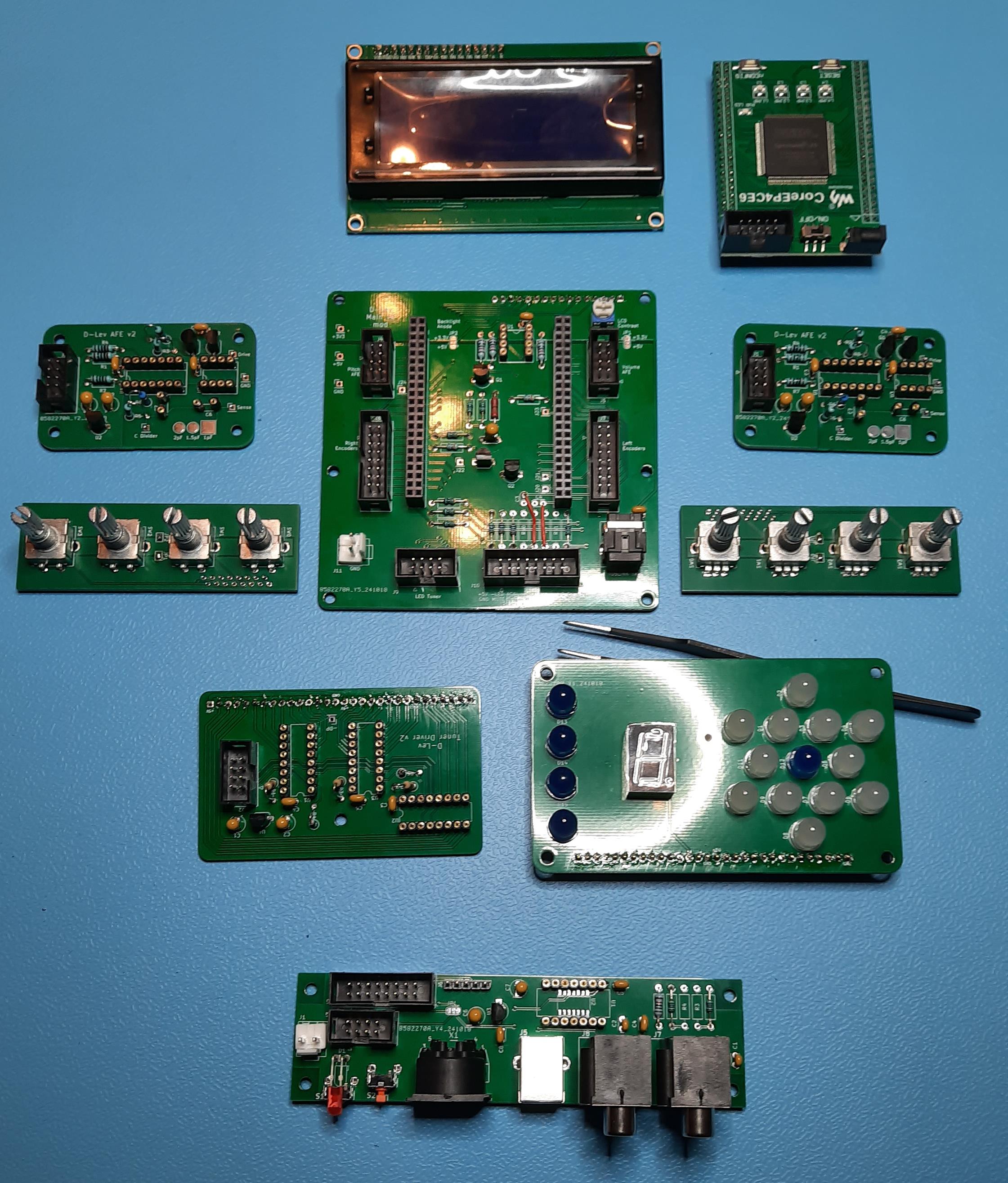
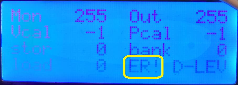
"- The encoders should respond without the AFE being connected? The fact the display shows the correct layout means the FPGA build and flash likely went ok?"

Yes, the encoders should work without the AFEs being connected.  The display information looks good.  And the normal looking values indicate the EEPROM is loading OK.

"- I shorted the ESD and ground pad on the encoder PCB (as discussed in previous post)."

Good.

"Anything I am missing or got wrong from my PCB encoder photos? Any debug hints? Suggested tests? I currently don't have an oscilloscope, but can get one (to look at PWM output signal from encoder)."

My guess is the encoder wiring is jumbled.  If you have a DMM, put it in volts mode, connect the negative lead to circuit ground, and look at the voltages on the encoders:

For the group of 3 pins: the middle pin should be ground, the outer two should be +3.3V.  Turning the encoder should cause the outer pins to go to ground and then return high.

For the group of 2 pins: one should be ground and the other +3.3V.  Pressing the encoder should cause the high pin to go to ground, releasing should make it go back high.

Good luck and welcome to the club!   And I'm always up for a video call!

Posted: 10/27/2024 6:02:44 PM
dewster

From: Northern NJ, USA

Joined: 2/17/2012

Rail To Rail AFE Drive?

While playing around with old unused analog oscillator topology, I noticed something interesting going on in LTSpice.

The above is a non-inverting buffer, powered via 3.3V and driven by a 3.3Vpp square wave.  Even when driving a 100 ohm load the output almost reaches the supply rails.  This is due to the inclusion of C2, which AC couples the Q3 & Q4 output drive transistors base leads.  Also important is to employ Q1 & Q2 as simple base-emitter diodes, leaving their collectors floating.  Spice investigation shows the input impedance is pretty much 2.2k / 2 = 1.1k, which is expected.  Output impedance is around (2.2k / 2) / beta = 8 Ohms, which is also expected.  Here it is on the bench driving a 10mH coil connected to a small plate antenna at 440kHz resonance, the input stimulus is via my FY6900 function generator:

For the yellow output square wave, pay no attention to "Vpp=5.20 V", the scope vertical is 1V / division, so it is actually 3Vpp.  The blue trace is at the antenna plate via my home-brew 100:1 HV probe, or around 400Vpp.  It only draws 2.8mA or so when driving the coil & plate.

When driving coils with a low voltage logic supply, it's good to get as much voltage swing as possible.  The square wave helps here too because the fundamental harmonic is larger than 3.3Vpp.  I need to experiment with this further to see if harmonic locking is an issue or not.

[EDIT] I must credit Vadim, he gave me the idea to use the base coupling capacitor from one of his posted schematics - which showed it in that position but not fully electrically connected.

Posted: 10/27/2024 7:23:53 PM
André

From: 30 km south of Paris (France)

Joined: 12/23/2022


Dewster : Honestly they'll probably be fine regardless, the D-Lev isn't too picky here.  I did have some issue though with the last spool of wire I ordered, it was double coat so the 2mH measured 1.7mH.  I should have at least put a dial caliper on the wire before winding coils as that would have revealed the extra thick insulation.

I measured 0.22 mm for the 0.20 mm wire and 0.27 to 0.28 for the 0.25 mm wire.
I made the coils to the theoretical length and counted the turns of the first two.
The numbers are very close to the theory.
So, I'm not expecting to have a wrong inductance value?

It seems to be fairly important to keep some tension on the wire when winding.  What are you using for coil dope?

For the tension, I simply used my finger on the coil and added a little more tension by holding the wire between my palm abd the other fingers.
I did exactly what you do on the video, including the "nail polish" to glue the ends of the coil.
Once the end wires are soldered and the coil is covered by the shrink tube, nothing can move.

What do you call dope ?

Posted: 10/27/2024 7:29:51 PM
gerbold

Joined: 9/26/2024

Today I connected everything, including some "stub" inductances of 1mH and 2mH, just to have something similar in place. Actually I wound them using a ferrite ring plus some 25 respective 50 windings. 

I get some noise out of the D-Lev, but nothing that I can controll. Neither pitch nor volume. It sounds a bit like a badly tuned radio in old days wt very high pitch. On the display I get the "ER!". According to the D-Lev manual, (page 54) the cure is a power cycle. Unfortunatelly the error appears right away after power on. It maes me aslo wonder that some values are out of bounds. I.e "Out" has a range of 0 or 1. Initially I loaded a configuration that I compiled on my own, playing with the seed. Finally I rolled back to the evrsion provided in the zip file, but with the same result.

Where can I start to track down the "ER!"?

The tuner has only one LED lit: the center of the star.

Your hint regarding C6 and snipping the pin of the potentioeter I followed. The same has been mentioned in the assmebly instructions. I found it in the KiCad folder. For me there was no need to snip the pin as I have a solder bridge that can connect 3.3V or 5V to this pin. I kept it open to isolate this pin.

The 1.5pF I need to connect.

Measuring the sine of the AFE should probably be my next step.

You must be logged in to post a reply. Please log in or register for a new account.