Let's Design and Build a (mostly) Digital Theremin!

Posted: 2/9/2025 8:52:11 PM
dewster

From: Northern NJ, USA

Joined: 2/17/2012

Aspect Ratio Post & T-Coil Program Updates

I just updated the aspect ratio post above: http://www.thereminworld.com/forums/T/28554?post=224518#224518

Also, my T-Coil program has been updated a bit (see the README file in the ZIP archive): https://d-lev.com/research/tcoil_v3_2025-02-08.zip

Posted: 2/9/2025 9:13:29 PM
dewster

From: Northern NJ, USA

Joined: 2/17/2012

PCBs as Plates & Panels

Ran across an interesting video where the guy was using PCBs as synth module faceplates: https://www.youtube.com/watch?v=UOQezMJ560o

I'm strongly thinking of using this for the D-Lev control panels and field plates.  Here is one possibility for the plates:

The front (left) would have a high contrast solder mask "target" on it to enable the player to more easily track it via peripheral vision.  The back (right) would be solid copper, and I'd probably solder some screws or similar to it to affix the coil, and the AFE would then be affixed to the other end of the coil.

Posted: 2/13/2025 7:38:23 PM
dewster

From: Northern NJ, USA

Joined: 2/17/2012

Coil Forms: PETG vs PLA

I wound two identical 1mH coils on 3D printed coil forms of 38mm diameter & 99mm long.  One form was printed in gray PETG, the other white PLA.  Wire used was 30AWG double coat green, winding length 79mm.  Clear nail polish to hold the ends, thin clear "battery" type shrink tubing covering the works.  28AWG Kynar wire wrap wire 150mm in length for the leads:

I was mainly interested to see if there was any Q difference on my test jig, but there doesn't appear to be.  PLA is more rigid, which is great for coil forms, but it melts at a lower temperature, which could bad if you leave your Theremin in a hot car.  Anyway, another minor mystery goes by the wayside.

Posted: 2/14/2025 2:12:37 PM
ILYA

From: Theremin Motherland

Joined: 11/13/2005

I don’t think there’s anything mystical about this. Dielectric losses will be greater if we place a dielectric in a region with the strongest electric field.

In the case of a solenoid, the strongest field is around the windings, i.e., outside. Inside, the field is practically zero. No field - no losses. Therefore, it doesn’t matter what the core is made of (unless, of course, it’s explicitly conductive).

Posted: 2/14/2025 5:10:19 PM
dewster

From: Northern NJ, USA

Joined: 2/17/2012

"I don’t think there’s anything mystical about this. Dielectric losses will be greater if we place a dielectric in a region with the strongest electric field."  - ILYA

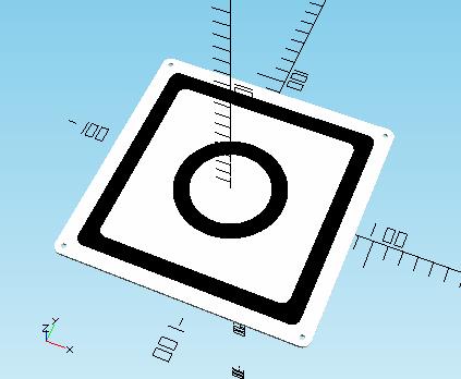
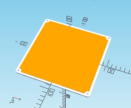
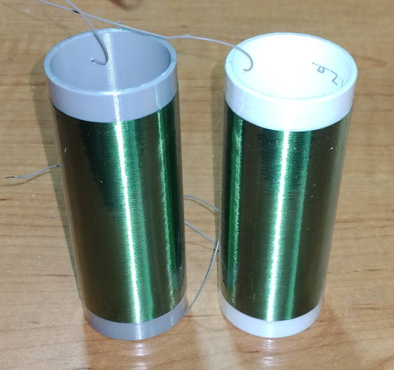
True, but these experiments are to find out the impact of various coil formers on Q.  3D printing really helps the winding process, particularly with finer wire on larger diameter formers.

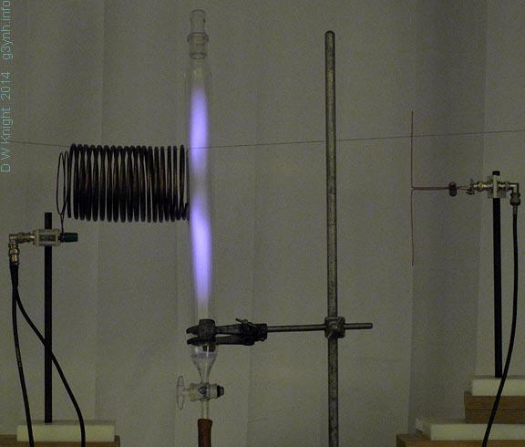
"In the case of a solenoid, the strongest field is around the windings, i.e., outside. Inside, the field is practically zero. No field - no losses. Therefore, it doesn’t matter what the core is made of (unless, of course, it’s explicitly conductive)."

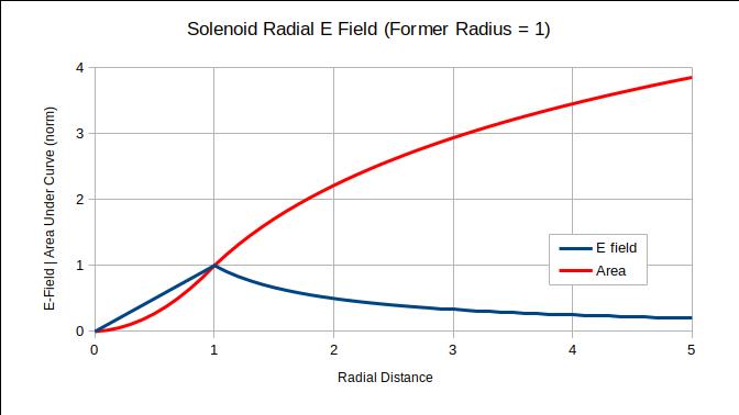
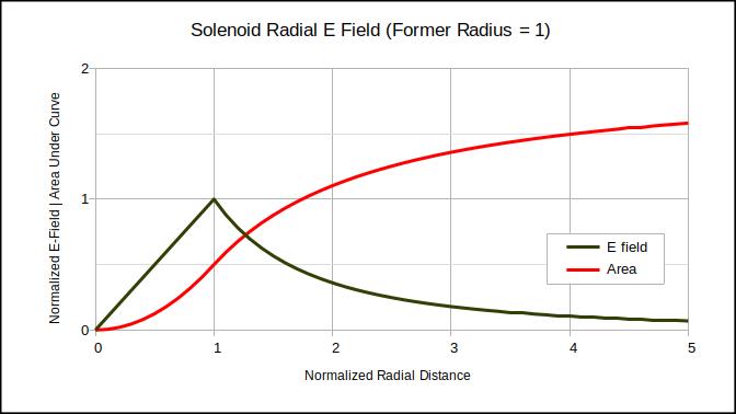
Hmm.  I assume you're talking about the electric (rather than the magnetic) field?  This says the E field inside a solenoid is proportional to the radial distance from the center, and the external field strength goes as 1/r: [LINK].  I've read that the magnetic field inside is uniform, and that the external magnetic field is largely zero.  My understanding is that non-conductive former materials will introduce electric field losses greater than those of vacuum / air.

Posted: 2/14/2025 9:17:29 PM
ILYA

From: Theremin Motherland

Joined: 11/13/2005

"you're talking about the electric"

Of course, about the electric field.

The radial distribution of the field can be clearly seen on the photo:

Posted: 2/14/2025 9:31:31 PM
dewster

From: Northern NJ, USA

Joined: 2/17/2012

"The radial distribution of the field can be clearly seen on the photo"  - ILYA

Which looks like it could be as they describe in the link?  Linear ramp up from the center to the windings, then 1/r?  I agree that this would put most of the electric field outside of the coil, but there is not a negligible amount inside to interact with the coil former material and degrade Q.  Hams talk about this, and they're a fairly practical sort.  I do appreciate your making me think about this more!

Posted: 2/15/2025 5:42:10 AM
ILYA

From: Theremin Motherland

Joined: 11/13/2005

"there is not a negligible amount insid"

Yes, inside the solenoid the field increases from the axis towards the windings, but it is relatively weak compared to the external field.

My boss never actually disagrees with me. He just says, “Yes, you’re right, but the effect is negligible.”

Posted: 2/15/2025 10:17:00 AM
dewster

From: Northern NJ, USA

Joined: 2/17/2012

"Yes, inside the solenoid the field increases from the axis towards the windings, but it is relatively weak compared to the external field."  - ILYA

Agreed!  I went ahead and plotted it:

The electric field of a solenoid is coaxial:

1. It is zero at the center of the solenoid. 
2. It increases linearly to the windings.
3. It then decreases as the inverse of the radius. 

Summing the area under the curve shows the bulk of the E field exists outside the solenoid.  The area here is normalized to the E field sum at the windings to make the graph easier to read.

The infinite sum of 1/r doesn’t converge, so I imagine the above only holds for an infinitely long solenoid?  I would expect the usual 1/r^2 in the far field, which does converge.

You must be logged in to post a reply. Please log in or register for a new account.