


Fred- I may need some advice on scope settings. If I need some guidance, you mind If I just email you directly? I probably wont get to this until at least this weekend.
Theremin Circuits Scratchpad
Posted: 10/11/2012 6:27:19 PM

From: Eastleigh, Hampshire, U.K. ................................... Fred Mundell. ................................... Electronics Engineer. (Primarily Analogue) .. CV Synths 1974-1980 .. Theremin developer 2007 to present .. soon to be Developing / Trading as WaveCrafter.com . ...................................
Joined: 12/7/2007
Yeah - Anyone who wants to email me from TW is welcome - my email is embedded in my picture (icon / avatar whatever - dont know the name for these things.. ;-)
I will see if I can find any details on your scope if you tell me what it is - make., model number etc - and if you can give full details about the probes etc you have / have made, this will help me or anyone else to give advice.
There may well be others here better able to advise on probing tube circuits - w0ttm for example - but I will do my best ;-)
Fred.
Posted: 10/11/2012 8:26:12 PM

The goal is to protect the scope front end from the high voltage and avoid loading the high Z bits. Grids are the most sensitive to this. The cap blocks the DC, and series resistance reduces loading.
The more series resistance, the better, within reason. Several megs would be nice. I have a special 10 meg, high voltage resistor that was used in a voltage divider to measure plate voltage in a very high powered tube amplifier.
If you listen to your theremin and detect very little or no difference in the sound with the probe on or off, then you are good. I suspect that there might be some minor frequency shifts in some probes. A few Hz should be OK.
Check calibration with a known voltage source and make a note of any variation. Almost every scope I've seen has a handy output on the front for just such a use. Mine has a 5 volt square wave, but any low voltage AC source will work, such as a 12 volt transformer.
My scope is rated at 300 volts DC input, and I have probes with a nifty little 10 X switch that should let me probe most tube circuits directly. I never do. I always insert a lot of resistance.
Scope bandwidth is important. You can still see the wave forms if the bandwidth is too low, but calibration goes out the window. Being a dual trace, your scope should at least have a 5 MHz bandwidth, probably more. The lowest bandwidth dual trace I've seen went to 10 MHz, and I've used it to view 30 MHz signals.
A word on safety.....
High voltage wants to kill you. One of the things I do is probe with one hand, with the other hand in my back pants pocket. This makes it impossible to have current flow from one hand to the other, with my heart in the middle. It's still possible to get a shock, but the results are much cussing, not death. Also, stand on something insulated so current can't flow from your hand to a foot, with other important body parts in it's path.
Be aware of your surroundings. If you do get a shock, you are likely to jump, and possibly bash into something that will hurt even more, or knock your chassis off the bench.
Rob.
Posted: 10/11/2012 9:44:32 PM

Note: I am not an engineer. The following might be full of errors..
edit: uups.. at least one error! I connected the 1n cap NOT to D/coil BUT to the opposite site of the coil (directly to PLUS). The waveform at S for the given schematic in a follow-up posting.
I must say that this transferred oscillator behaves quite brave. The last image shows some possible waveforms with both the source connected to the mixer. Even more waveforms showed up by using S/D, D/S, D/D and by connecting the antenna to the other oscillator. Dirty/unstable behavior by using G (or the opposite site of the 10K resistor).
I have had two of these on hand. It is a kit commonly to be used for AM radio frequencies.
Filterspulenbausatz, 7 mm bis 1.8 MHz
.. and rolled transformers. Both windings with 120 turns. Inductivity with the core completely srewed in:
Single: about 150uH
Series: about 650uH
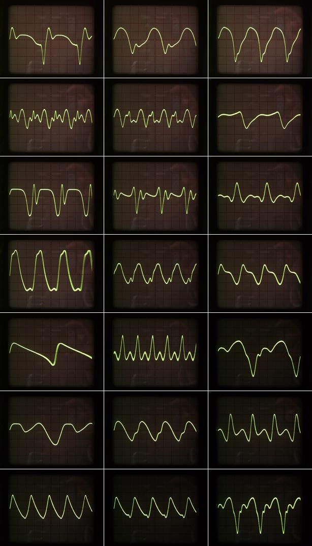
This is the schematic by Fred, with the added mixer:
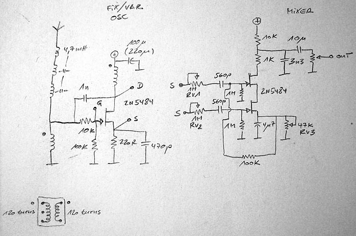
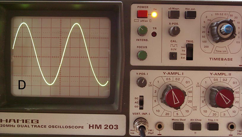
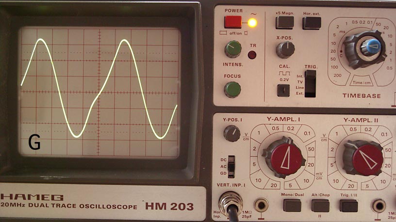
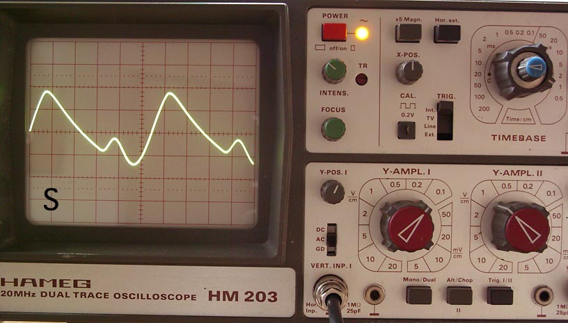
These are the waveforms appearing at:
D:
G:
S:
and some resulting waveforms by playing around with the three pots RV 1/2/3. Both mixer inputs "S":
Posted: 10/12/2012 7:55:35 AM
From: Eastleigh, Hampshire, U.K. ................................... Fred Mundell. ................................... Electronics Engineer. (Primarily Analogue) .. CV Synths 1974-1980 .. Theremin developer 2007 to present .. soon to be Developing / Trading as WaveCrafter.com . ...................................
Joined: 12/7/2007
Thank you, Dominik !
That looks extremely promising IMO, the addition of those variable resistors really brings the mixer to life!
Fred.
- Interesting.. I have re-run my simulation of the oscillators and both the G and S waveforms are quite different to what you are actually seeing - what you are seeing (reality) is far more musical than what my simulation shows ;-) - The S signals in particular - rich in both odd and even harmonics, with ramp charactaristics which look like the harmonics will be reducing in a musical way.
In the simulation, both odd and even harmonics are strong, but 2nd and 3rd harmonics exceed the fundamental, and higher harmonics are all over the place WRT amplitudes, with 6th, 7th and 9th being higher than is acceptable.
My simulation gives: 1= -10db, 2= -5db, 3= -6db, 4= -17db, 5= -15db, 6= -22db, 7= -22db, 8= -32db, 9= -31db, 10= -42db
This is the thing about simulations - they are great for getting on "on the path" - but not so good at accurately modeling final real results - its down to the quality of the models - I suspect that the fet models are not accutately computing miller capacitance, nor are the coupled inductors behaving as real ones do.
But I am really glad that the real behavious is so good.
Posted: 10/12/2012 12:44:13 PM
Oh yes - i have listened to the output! It seems to me that RCA´s and such produce a decent spike or plain part or whatever each cycle, which i at least was getting an idea of with some settings. However - amazing. Quite vocal character, bassy or thin or inbetween, nasal, .. maybe i will record something.
I am an amateur with the scope. Just a 10K resistor between the test points and the scope. And still it is on breadboard, maybe not the best way to predict the finished circuit boards reality when it comes to theremins.
By adjusting RV1/2 also the frequency changed more or less. Does the (quasi dual gate) mixer also serve as var/fixed oscillators decoupling device? To me it looks like that and i wonder, because in comparison to a theremin with buffered oscillators the zero beat zone is quite huge. "Behind" the zero beat the sound would start again, but just if zero beat was adjusted relatively close to the rod. Thus it behaves like being non-buffered, though the lowest range does not seem to be compressed as being likely (at first sights)..
Posted: 10/12/2012 2:29:29 PM

Dominik - thank you for your great and inspiring work!
I think that you will naturally see some coupling between the oscillators, be it through the common power supply, through the internal capacitances and some capacitive DS-Feedback of the upper mixer FET or simply through the air.
It may be an interesting information that Lev Theremin even added a variable capacitor between both oscillators' outputs in Clara's and Lucie's instruments to increase the coupling...
I think that he saw no interest in going lower than 100Hz AF because the speaker couldn't handle it. Thus he made the coupling somewhat stronger to obtain a more interesting waveform and more tuning stability.
Posted: 10/12/2012 2:46:42 PM
Whoa! Good work Dominik- Did you do that all last night? I definitely need some of that German efficiency.
So it looks like we have a good candidate- the wide range of possible waveforms achievable by playing w/ the pots looks very promising....
I realize all you guys want to stick with components in the Eagle library/ digikey catalog ... I still think that tiny "can" inductors may be a problem. AFAIK, they just arent constructed the same way as the RCA oscillator coils (ie- 2 oppositely wound layers-one on top of the other)
Just my instinct ( and Howie's advice) -but I feel that this contributes something to the RCA sound. ( tho' Im most likely totally biased- and probably the only large coil advocate (just for pitch oscillators.)
that being said....Obviously, your solution is working. Awesome. I think that this is a big break-thru. Ill work on getting an "old School" coil model together and we can compare.
Posted: 10/12/2012 5:37:09 PM
From: Eastleigh, Hampshire, U.K. ................................... Fred Mundell. ................................... Electronics Engineer. (Primarily Analogue) .. CV Synths 1974-1980 .. Theremin developer 2007 to present .. soon to be Developing / Trading as WaveCrafter.com . ...................................
Joined: 12/7/2007
".. and rolled transformers. Both windings with 120 turns. Inductivity with the core completely srewed in:
Single: about 150uH Series: about 650uH" - Dominik
Interesting results - 120 turns @ 150uH gives AL = 10.4 (quick calculator here) and 240 turns computed with the same AL gives 600uH - So your transformer is giving the right ball-park.
I have just rewired a 42IF106 transformer giving it 70 turns per winding, with the slug about mid way I get about 150uH per winding with total (series) of about 600uH.
"Just my instinct ( and Howie's advice) -but I feel that this contributes something to the RCA sound. ( tho' Im most likely totally biased- and probably the only large coil advocate (just for pitch oscillators.) " - Hobbs
You might be right, im not sure.. At these frequencies I dont really see how the one obvious difference (capacitance) would be significant - And at these signal / current levels, I dont see the BH charactaristics of a ferrite core would be significant..
But they may be.
"AFAIK, they just arent constructed the same way as the RCA oscillator coils (ie- 2 oppositely wound layers-one on top of the other)"
No, the construction is completely different - I think that the physical charactaristics / construction of the RCA tank transformer was determined by the available technology - the double layer construction facilitates close coupling required to give the total inductance and to provide sufficient feedback.
The windings of these 'cans' is on a plastic former over a ferrite slug, and in some cases covered by a ferrite tuning slug - it would be difficult to make a transformer more different in construction to the RCA's transformer!
But functionally, well, I dont (yet) see any fundamental difference - except that one can tune these transformers and therebye eliminate the trimming capacitors.
I personally think that the mixer is where most of the magic happens - I think the oscillator / antenna design's primary 'magic' is in its stability and linearity, and the mixer creates most of the rest.. not all though ;-)
Fred.
You must be logged in to post a reply. Please log in or register for a new account.