Tell us about your experience with Open.Theremin

Posted: 11/24/2013 1:58:38 AM
FredM

From: Eastleigh, Hampshire, U.K. ................................... Fred Mundell. ................................... Electronics Engineer. (Primarily Analogue) .. CV Synths 1974-1980 .. Theremin developer 2007 to present .. soon to be Developing / Trading as WaveCrafter.com . ...................................

Joined: 12/7/2007

[Sorry folks - this aint really about open.theremin - its a technical diversion, hijack at worst, a bit OT at best! :-]

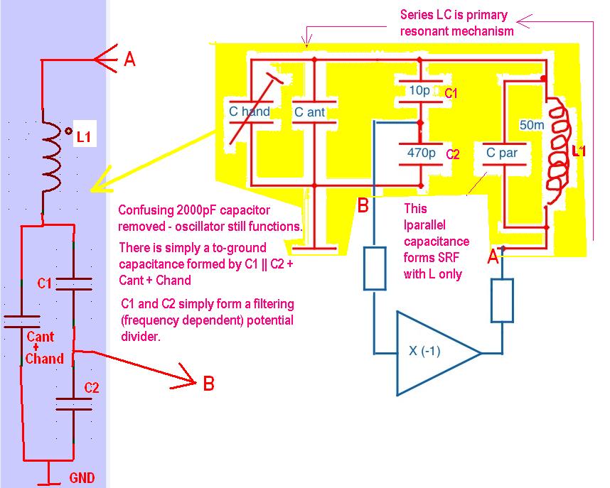
"It naturally runs when you remove C3 and C4. Then there is the capacitive divider formed by C_ant and C5 in parallel with the coil, a simple Colpitts oscillator... still no series resonance... there is a phase shift of 180° between V_drv and V_ant." - Thierry

Hmm .. Are you saying that all oscillators equate to parallel resonant topologies?

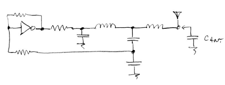
C5 was removed in my 2nd experiment - when I said "I just ran the simulation without the 2000pF capacitor (as in, I removed that C but made No other changes)" it was C5 (on my circuit) I was talking about - ok, on Dewsters original it was 2n, on mine it was 1n.. My sole reason for 'redesigning' the oscillator was that my logic models dont run - I have models I constructed myself, but felt that putting a home-made sub-circuit into a hex inverter symbol and running simulation on this could be misleading / dishonest.. At least using a manufacturers spice model anyone should be able to replicate the simulation - IMO, the active part is just there allow proof of concept.

C'ant goes to ground - the coil is driven from one side via R7 / D3 (on my circuit this was done to balance the driving Z, as the 393 is an open collector part)..

I really dont see how C'ant is in parallel with the coil.

But im not going to argue anymore - I have work I should be doing! ;-)

Fred.

(even with C5 in circuit, I dont see this as in parallel with the coil - its on the drive side of the coil to ground, and with the drive resistor is merely acting, I think, to smooth the drive waveform with some concequential shifting of the drive phase - but removing it made no real difference as far as I could see...)

I have not studied this oscillator closely, but Dewster has.. I really dont care what type or class it is - to me though, it looks intuitively like a series resonant topology.

Posted: 11/24/2013 2:50:54 AM
dewster

From: Northern NJ, USA

Joined: 2/17/2012

This is how I think about the oscillator.

The drive resistor sets current drive into the coil.  You set this to somewhere between 220 and 1k ohms, regardless of the inductance value, to get 100V+ swing at the antenna.  The drive resistor with the following C forms a delay / LPF.  You set this to get maximum voltage swing at the antenna, which gives 90 degree phase lag.  The left inductor "sees" the right inductor connected to the antenna and 10pF or so to ground and resonates with them both, causing a large voltage swing at this node (~1/2 the V swing at the antenna IIRC).  The right inductor "sees" the drive on the left and the antenna capacitance, which it resonates with.  The two capacitors also form a voltage divider, knocking the large voltage swing down to less than the CMOS supply rails.  This is fed via a resistor to the input of the inverter, which has large feedback resistor.  This resistor sets an upper limit on the inverter gain (for stability) but more importantly biases the capacitive divider about the threshold point of the inverter.

The nice things: It seems to be self-starting, and approaches the sensitivity possible for a single unloaded, series L driving the antenna capacitance.

The bad things: The LPF C needs to be resized for significant antenna capacitance changes.

The coil on the left is definitely operating in series mode, as the drive side is much lower impedance than the capacitive side.  It works fine without the EQ coil, but is maybe 2x more sensitive with it because the sense capacitor is then largely unloaded.

Will it work without the C to ground?  Yes, but the swing at the antenna won't be maximal.  A quadrature detector is necessary if you really need to remove this C.  Removing the C means more harmonics get into things, but it also removes the tuning of C, so you can put any antenna on it you want without retuning.

Posted: 11/24/2013 3:00:37 AM
FredM

From: Eastleigh, Hampshire, U.K. ................................... Fred Mundell. ................................... Electronics Engineer. (Primarily Analogue) .. CV Synths 1974-1980 .. Theremin developer 2007 to present .. soon to be Developing / Trading as WaveCrafter.com . ...................................

Joined: 12/7/2007

Hello Dewster ;-)

I thought I understood - until you added that extra inductor! LOL ;-)

Fred

"Will it work without the C to ground?  Yes, but the swing at the antenna won't be maximal.  A quadrature detector is necessary if you really need to remove this C."

Oh, I have no need to remove that C - My only reason for doing so was to confirm my understanding of the oscillators operation.. I never saw that C as in any way in parallel with the inductor - but needed to be sure I wasnt going crazy!

Fred.

Posted: 11/24/2013 3:04:45 AM
dewster

From: Northern NJ, USA

Joined: 2/17/2012

The way to tell series from parallel LC modes is to examine the voltages across the L and C.  If the voltages are in phase it is parallel.  If they are 180 degrees out of phase it is series.  (Though for this test to always be true I believe you have to keep the voltage swing within the supply limits - I'd have to simulate it to be sure.)

(Ignore the above, I need to think about it some more.)

I want to add also that the oscillator is fairly insensitive to the matching of series tank and EQ coil values.  2:1, 1:1, 1:2, etc. and anything in between and outside of this even all work fine, but 1:1 is probably the easiest.

The extra inductor looks complicated, but it really only acts to unload the antenna from the tank (and of course lower the resonant frequency due to the increased inductance).  This is why I'm interested in pursuing single coil series resonant topologies with no capacitors other than the antenna and no loading other than a small non-resonant sense winding near the drive end.  The sensitivity can be a bit higher, and the single coil can be air core, physically placing some distance between the drive and business (antenna) ends, likely further enhancing sensitivity.

Posted: 11/24/2013 3:32:13 AM
FredM

From: Eastleigh, Hampshire, U.K. ................................... Fred Mundell. ................................... Electronics Engineer. (Primarily Analogue) .. CV Synths 1974-1980 .. Theremin developer 2007 to present .. soon to be Developing / Trading as WaveCrafter.com . ...................................

Joined: 12/7/2007

"The way to tell series from parallel LC modes is to examine the voltages across the L and C.  If the voltages are in phase it is parallel." - Dewster

Thats what I thought - but have been doubting my memory of late.. Looking at the waveforms on my simulation (my 393 version which is topologically identical to your design) the voltage on the antenna is 180 degrees out of phase with the drive voltage - is this proof that its a series resonant oscillator? YES/NO (LOL ;-)

"The extra inductor looks complicated, but it really only acts to unload the antenna from the tank. "

Ok - the cause of my confusion! - I thought you were engaged in a tankless task!

Fred.

Posted: 11/24/2013 3:49:56 AM
dewster

From: Northern NJ, USA

Joined: 2/17/2012

"is this proof that its a series resonant oscillator? YES/NO (LOL ;-)"

It's getting late and I'm not thinking straight, but yes, the antenna voltage should lag the CMOS inverter output by 180 degrees.  The RC drive point should be right in the middle.  This might be easier to do with two cascaded RC elements (45 degrees + 45 degrees)?  I have to think about it tomorrow.

Posted: 11/24/2013 4:21:11 AM
FredM

From: Eastleigh, Hampshire, U.K. ................................... Fred Mundell. ................................... Electronics Engineer. (Primarily Analogue) .. CV Synths 1974-1980 .. Theremin developer 2007 to present .. soon to be Developing / Trading as WaveCrafter.com . ...................................

Joined: 12/7/2007

"but yes, the antenna voltage should lag the CMOS inverter output by 180 degrees. " - Dewster

Yes, my understanding is that the voltage at the antenna, for a series resonant circuit, will be in-phase with the drive signal below Fr, but go rapidly to 180 degrees out of phase at / above Fr, For your oscillator to work (if its working with a series resonant network and not through some other mechanism) I think that at Fr it must be 180 degrees out of phase..

It probably gets more messy if one has any significant C in parallel with the L -  provided this stray capacitance does not push the parallel resonant point too close to (or lower than) the series resonant frequency.. But thats probably a whole other subject, involving horrible maths.

Anyway, never did get that work done, and am too tired now -  it was a somewhat useful digression - But I think I will back away at this point.. He that fights and runs away, lives to fight another day!

;-)

Fred.

Posted: 11/24/2013 2:54:32 PM
gaudi

From: Switzerland (CH)

Joined: 8/6/2010


LOL - love your technical diversion with a bit of OT. I am far from understanding your dispute on topologies, kind of understand the possibility to put a coil in series with the antenna and an "antenna coil only design" would be my favorite (to overcome "bad engineering practice" :-). Will do some breadboarding I guess...  dimensioning and flexibility with different type and length of antennas might be a challenge.

Open.Theremin is known to be verry flexible with different antennas - see Knitting-Machine-Theremin :-)


Posted: 11/24/2013 6:06:01 PM
dewster

From: Northern NJ, USA

Joined: 2/17/2012

A bit more OT ramblings (very sorry).  I think most Theremin oscillators use a parallel tank because the feedback is in phase (0 degrees).  This means the amplitude will likely be constant over frequency, but the oscillator could stall, so you have to be lucky / careful in the design phase to address this (the EWS oscillator is pretty good in this regard, but I was able to stall it when fooling around with the tuning).  Series drive means you have to deal with the 90 phase shift between the tank oscillations and the drive, which in the circuit I presented means the amplitude will vary somewhat with frequency due to the fixed RC delay being fixed rather than 90 degrees for all frequencies.  The way around this is a quadrature detector (XOR phase detector).  Given this, the oscillator should never stall under any reasonable conditions and the amplitude will be constant over frequency (I've seen this on the bench).

This morning I was playing with the circuit I presented, and the RC capacitor seems necessary for oscillation (at least in the configuration I was playing with).  Grasping the antenna firmly makes it operate at the second harmonic, when releasing the antenna it pops back to the fundamental.  I used this circuit to measure capacitance, but haven't worked on developing it further as I don't have an immediate need for 100% analog oscillators at this point.

High Q is necessary in any series coil configuration for good voltage multiplication.

This thread diversion is very interesting to me because I'm wondering if there is more information to be had from a heterodyned signal vs. examining the operating point of my DPLL (frequency subtraction vs. mathematical subtraction).  I.e., is it better to heterodyne down - not to baseband (null) but to some IF - and do the detection, or is it equivalent (or better, or worse) to just measure the frequency and subtract a number from it?  Heterodyning obviously gives you much wider frequency changes, but at lower frequencies, so there is obviously a trade-off in terms of how many samples (per second) you get to use in your digital calculations (for averaging, etc.) but that doesn't seem like the whole story.

Posted: 11/24/2013 6:48:31 PM
FredM

From: Eastleigh, Hampshire, U.K. ................................... Fred Mundell. ................................... Electronics Engineer. (Primarily Analogue) .. CV Synths 1974-1980 .. Theremin developer 2007 to present .. soon to be Developing / Trading as WaveCrafter.com . ...................................

Joined: 12/7/2007

OT - I have removed this posting related to a different possible theremin topology - it shouldnt have been here... When I have my thoughts together I may start a seperate thread for it.. for now I will dump it somewhere here : http://www.element14.com/community/groups/theremin-general-resources - but  it may be a deliberately not easy to find until I have it further developed.

Anyone who saw it and REALLY wants, I can email it to them..

You must be logged in to post a reply. Please log in or register for a new account.