Crazy (?) theoretical / technical ideas

Posted: 12/7/2013 10:44:26 PM
FredM

From: Eastleigh, Hampshire, U.K. ................................... Fred Mundell. ................................... Electronics Engineer. (Primarily Analogue) .. CV Synths 1974-1980 .. Theremin developer 2007 to present .. soon to be Developing / Trading as WaveCrafter.com . ...................................

Joined: 12/7/2007

Over on another thread, Dewster presented some "Crazy" technical suggestions and numbered these crazily..

Thinking about electronic tuning of theremins, I have had a few idea I have never seen anyone do, which look crazy -

And I thought .. A thread for potentially completely crazy ideas which just might work, and would like to invite anyone able to comply with the "rules" I am going to present, to submit them..

The rules:

There must be some thought process behind the idea - This is a theory / electronics / science / maths FOR THEREMINS forum.. So no circuits or whatever (Please!) which are just a collection of components with a "what will this do?" or a "this is a time machine - dont know how its supposed to work, I was just inspired"

You must be able to explain your theoretical thinking on anything you present - flawed thinking is fine.

----------------

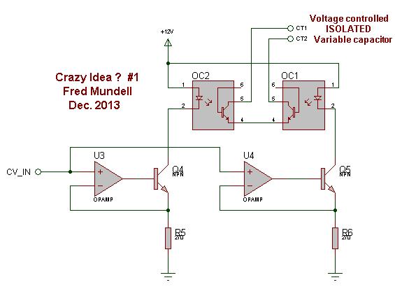
Below is my starting contribution - its a pair of opto isolators wired such that one transistor will always be reverse biased whatever polarity the connection to the "VC Capacitor" terminals are.

I hypoothesise that this will behave like a capacitor, and that by controlling the LED current, the width of the P Channel region 'between' the Emitter and collector will vary - as this width is controlled by light, there is no electrical coupling - so its an isolated current / voltage controlled capacitor.

Each isolator has a reverse breakdown voltage - cheaper opto isolators usually have this at about 30V max . they can have much higher voltages I think. So this VC capacitor could be connected directlt to some theremin antennas (?) .. Series diodes with high revers voltage could probably be added for higher antenna voltages.. they could stop destructive breakdown currents but im not sure theyd work - not sure if excess reverse voltage has some other destructive action.

I have simulated this circuit with a spice model from the web, and to my great surprise it worked.. But I do not trust this at all - because I havent found the required data to construct a behavioural model for an OC used in this way..

My simulation does however behave how I would expect - there is a large capacitive change (which I monitor in the simulation by change in oscillator frequency) - far greater than I get from standard reverse biased diodes  - My understanding is the the base on opto transistors is much larger than on standard diode or transistor junctions.. This is to optimise light collection and has a down-side of slowing the speed of the devices - low cost ones can be as slow as 5us, and one reason is the large base capacitance.

Posted: 12/12/2013 6:00:01 PM
dewster

From: Northern NJ, USA

Joined: 2/17/2012

That's pretty crazy Fred!  Could you put the LEDs in series and use a single VCCS?

Posted: 12/12/2013 6:17:07 PM
dewster

From: Northern NJ, USA

Joined: 2/17/2012

Not sure how crazy this idea is, but here goes:

The thread here at TW regarding the Open.Theremin has been quite informative.  One thing revealed in the schematic is that the pitch heterodyning frequency (i.e. local oscillator) is derived from a 8MHz crystal going into a 2^4 divider, which yields 500kHz.  Another output of this same divider is a "sample clock" time base marker at 2^8, which yields 31.25kHz.  The volume side uses a separate 7.3721 crystal divided by 2^4, which yields 460.7625kHz.

My crazy idea is this: do the rigid local oscillator and sampling frequencies have something to do with the anecdotal evidence that the volume and pitch sides don't seem to interact much if at all, even with the antenna leads intertwined?

Posted: 12/12/2013 9:07:52 PM
FredM

From: Eastleigh, Hampshire, U.K. ................................... Fred Mundell. ................................... Electronics Engineer. (Primarily Analogue) .. CV Synths 1974-1980 .. Theremin developer 2007 to present .. soon to be Developing / Trading as WaveCrafter.com . ...................................

Joined: 12/7/2007

" have something to do with the anecdotal evidence that the volume and pitch sides don't seem to interact much if at all, even with the antenna leads intertwined?" - Dewster

Not sure whether that anecdotal evedence is true or where it comes from, but I cannot see it being true..

If one has pitch and volume antenna leads intertwined, there will be capacitive coupling between them - forgetting about frequency interactions for the moment, lets say one had 5pF coupling, and moves the volume hand close to its antenna while trying to play a bass note softly - the movement of the volume hand (and resulting comparatively large capacitance change on the volume antenna) compared to the miniscule capacitance change which is present on the pitch antenna (due to the hand being distant from this antenna) will, even with only slight capacitive coupling between the two antennas (via the intertwined leads) cause the pitch to vary as the volume hand moves.

Again, it comes to precision requirements versus "messing about" requirements - the effect of the pitch antenna on the volume is not likely to be noticed - but the effect of volume hand movement on the pitch is, IMO, certainly noticable -

One other IMO significant problem, particularly if the players ground coupling is poor, is that even if there is no (or minimal) capacitive coupling between the 2 antennas (either due to wiring or their proximity) the players volume hand capacitively couples to the theremins internal ground (worse if the theremin is enclosed in a metal / conductive enclosure) and again, this change in player coupling will raise the pitch.

I think the thing which mitigates somewhat against these problems, is that they increase as the volume gets lower - If the volume antennas null is set some distance away from the volume antenna, the influence is greatly reduced - its only really when the volume null is close to the antenna that one is likely to hear severe pitch bend as the hand approaches the volume antenna.

Another reason perhaps why Lev chose "Near = softer" rather than "Near = louder" for the volume antenna.

Fred.

"Could you put the LEDs in series and use a single VCCS?"

Yes, you could - but it requires a higher voltage to overcome the Vf of the LED's - If using a 5V supply this starts to become a bother ;-).. I like to keep my options open .. Also, the ability to trim the resistors could be useful - Opto's (even if in the same package) have hugely differing charactaristics - I was thinking of perhaps reducing R5 and R6 to say 150R, and having a trim potentiometer connected to the botton of these, with its wiper grounded - that way one could balance the optos if required. I do tend to go for overkill - but I also like to keep parts "unshared" as much as possible - so sticking a dual opamp in instead of a single, and adding an extra transistor and resistor, having the option to trim, and keeping all the components exclusive to that subcircuit is just an automatic part of my design process.

But at this time I really dont know if the idea will work anywhere except in simulation ;-) .. For simulation though its a great help (whether it works in practice or not) because there is no "Voltage controlled capacitance" primitive (AFAIK) in the SPICE arsenal - Using this crazy idea gives me the ability to run my full PLL simulation (I cannot get models for reactors, and simulating varicaps is a right royal pain in the behind!) - This lets me "build" the whole system - if I need to change the tuning mechanism because the optos dont work in practice, at least I have most of the other bits of the system sorted, and can modify that if needed..

Posted: 12/12/2013 10:56:45 PM
dewster

From: Northern NJ, USA

Joined: 2/17/2012

"Not sure whether that anecdotal evedence is true or where it comes from, but I cannot see it being true.."  - FredM

I believe that's what RoyP was reporting over on the Open.Theremin thread.

"Another reason perhaps why Lev chose "Near = softer" rather than "Near = louder" for the volume antenna."

Oh!  I learn at least one fundamentally new thing every day here at TW!

Posted: 12/12/2013 11:52:28 PM
FredM

From: Eastleigh, Hampshire, U.K. ................................... Fred Mundell. ................................... Electronics Engineer. (Primarily Analogue) .. CV Synths 1974-1980 .. Theremin developer 2007 to present .. soon to be Developing / Trading as WaveCrafter.com . ...................................

Joined: 12/7/2007

"Oh!  I learn at least one fundamentally new thing every day here at TW!" - Dewster

LOL ;-) .. My comment about Lev is entirely a sudden hypothesis that popped into my head as I was writing the above - I have absolutely no idea if there is any truth in it! ;-)

There has been discussion before about why Lev chose this volume orientation - and it seemed like a bad choice to me, but some musicians argued otherwise. I had a lot of bother with pitch shift due to theremin coupled ground 'fields' on some early designs (particularly before I fully understood the importance of a good player-body-ground coupling) when I had quite insensitive volume antennas and the hand was closer to this antenna than it should have been..

But as to whether Lev had the same difficulty and reversed the sensing to overcome that problem, well its pure unfounded speculation on my part!

"I believe that's what RoyP was reporting over on the Open.Theremin thread"

Just had a look at that posting (had somehow missed it)

"No Degrading effect on performance" were the words Roy used - And I believe this - Or rather, I believe "No noticable degrading effect on performance under the conditions I used to test the theremin" -

And this is the crunch IMO - Everything about the theremin is so finely balanced, that one can get great results under one set of circumstances but get noticably inferior results if you simply change anything - Something as simple as changing the null position for the volume antenna, for example.

So many traps for the unwary! You play your theremin with the volume null set at say 20cm - thats how you play - you dont dream of trying it with the null set at 5cm... Someone with a different playing style comes along and gets pitch bend from the volume antenna ;-)

All fine if you are only making one theremin - not so fine if you ship a batch and get 20% returned because theres "a problem".

Posted: 12/17/2013 2:01:18 PM
dewster

From: Northern NJ, USA

Joined: 2/17/2012

"Everything about the theremin is so finely balanced, that one can get great results under one set of circumstances but get noticably inferior results if you simply change anything"  - FredM

Yes, you make very good points.

Posted: 12/17/2013 2:22:59 PM
dewster

From: Northern NJ, USA

Joined: 2/17/2012

Crazy idea #6965

If you are using UHF connectors for your Theremin antennae (highly recommended, particularly over the usual plumbing solutions) the panel mount connector is likely an SO-239:

The inner conductor can be used to transport the antenna signal, and you are free to do what you wish with the outer conductor.  If you ground it you will be introducing 3 to 4 pF of load to the antenna, which is significant but perhaps not too onerous (though if you include a 90 degree elbow and the PL-259 male connector on the antenna you're up to a whopping ~9pF).  You might use this ground to do passive shielding on the antenna, which would introduce even more static capacitance.  I haven't played with shielding at all but intend to in the future.  One could put a wire or jumper inside the Theremin case to enable or disable this grounding in the field.

Here's the crazy idea: Don't ground the outer connector conductor, instead use it to capacitively sense the antenna signal voltage.  That is, monitor the antenna voltage swing by looking at the unloaded voltage on the outer connector conductor, and use this as an integral part of the oscillator (feedback).  One downside here is you would be exposing sensitive circuitry directly to a harsh ESD environment.  Another possible downside is the antenna voltage lags the drive waveform by 90 degrees.

I'm not advocating nor entertaining the use of the connector in this way (I prefer direct low impedance feedback within the oscillator itself) but wanted to at least note the possibility of doing so.  If you've ever poked around a Theremin with an oscilloscope you probably know that the antenna voltages can be large enough to build an oscillator with no visible means of feedback.

[EDIT] I just breadboarded it and it works!

Square wave drive in, nice 2V p-p quadrature sine wave out (before the second output buffer).

This could form the basis of a very inexpensive Theremin.

Posted: 12/19/2013 1:17:14 AM
FredM

From: Eastleigh, Hampshire, U.K. ................................... Fred Mundell. ................................... Electronics Engineer. (Primarily Analogue) .. CV Synths 1974-1980 .. Theremin developer 2007 to present .. soon to be Developing / Trading as WaveCrafter.com . ...................................

Joined: 12/7/2007

Hi Dewster -

I thought you had a genuinely crazy idea - then you go and breadboard it!  ;-)

Ok - its clever and crazy!  ... My question though is this - what is the advantage compared to just tapping directly off the antenna?..

the 50-239 is acting as a capacitor - 3 to 4 pf - so replacing the 5pF with a say 2.7pF and connecting this to the antenna will give about the same results..

The thing which bothers me about the 50-239 as a capacitor is its thermal charactaristics - I doubt it will be NPO.. I can see no advantage in its use as a capacitor (although one could eliminate the 5pF and connect direct to the 50-239 therebye saving one component..

I think what you have done is extremely interesting, quite crazy, but thats it - What am I missing ? I simply cannot see any advantage in doing this.. And I cannot see how "This could form the basis of a very inexpensive Theremin." - AFAIKS it wont make any difference to cost at all..

Posted: 12/19/2013 4:54:37 AM
dewster

From: Northern NJ, USA

Joined: 2/17/2012

"My question though is this - what is the advantage compared to just tapping directly off the antenna?"  - FredM

Good question!  I agree the thermal characteristics of it might not be the best.  And it probably won't change cost much, if at all. 

Grasping at straws: It might load the antenna a bit less?  It's a natural feedback point?  I don't know.  I guess that's why I stuck it over here in the crazy ideas bin.

As you say the 5pF does present the antenna with ~5pF in series with 5pF, which is ~2.5pF, so the sensitivity isn't lowered very much due to loading (I've seen a noticeable noise increase going below about 10pF right off of the antenna).  The waveform from this actually looks a little cleaner than the inductive winding I'm investigating.

One thing that's nice about quadrature detection like this (and inductive pick-off) is that any drive spurs on the supply (if you are using the same hex inverter package to drive the tank) end up far away from the zero crossing points on the detection side (if you are squaring up the result and feeding it to logic).

You must be logged in to post a reply. Please log in or register for a new account.