Crazy (?) theoretical / technical ideas

Posted: 12/28/2013 2:12:30 AM
FredM

From: Eastleigh, Hampshire, U.K. ................................... Fred Mundell. ................................... Electronics Engineer. (Primarily Analogue) .. CV Synths 1974-1980 .. Theremin developer 2007 to present .. soon to be Developing / Trading as WaveCrafter.com . ...................................

Joined: 12/7/2007

Hi Dewster,

Re #6966 - Not at all crazy, been done (I saw someone at one of Lydia's classes with a T-Grounded mic stand), I always ground my stands - works well.

IMO, having anything "floating" (ungrounded metal near a theremin) is a bad idea, as it will couple capacitively to player / objects in unpredicatable ways... Usually large objects have enough capacitive coupling to ground that they wont cause problems - but mic stands can couple to the player without being well coupled capacitively to ground.

So not crazy!!  ;-)

Posted: 12/28/2013 3:37:41 AM
FredM

From: Eastleigh, Hampshire, U.K. ................................... Fred Mundell. ................................... Electronics Engineer. (Primarily Analogue) .. CV Synths 1974-1980 .. Theremin developer 2007 to present .. soon to be Developing / Trading as WaveCrafter.com . ...................................

Joined: 12/7/2007

Dewster -

Thanks to your clever CMOS oscillator design ( the last one where you effectively created a differential amplifier using two unbuffered inverters) I have been exploring CMOS in linear mode.. Its one of these topics I left behind many years ago when good quality opamps became available at reasonable prices - as a hobbyist did all sorts of stuff with CMOS - but sort of threw the baby out when I started "real" design.

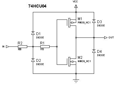
I managed to find a SPICE file for the PMOS and NMOS transistors used in the 74HCU04, and created a working model which behaves exactly as all the app notes describe - and have been playing with simulations using these parts..

Some things I have found: (using 5V supply)

1.) Amplifier - With 1V P-P input, the behaviour is quite linear, and there is not much distortion.

2.) Overdriving the input gives a soft-clipping response - I have been playing with simulations using these amplifiers as HF amps (>100kHz <1MHz) to buffer theremin oscillators..

3.) CRAZY IDEA - Drove a seperate 74HCU04 with its VCC biased with a resistor from a variable DC supply, and AC coupled a signal into VCC.. Started out by sticking REF oscillator into VCC and Var Oscillator into an amplifier constructed from one inverter.. And yes, it formed a really interesting mixer - by altering the VCC supply (bias) voltage and AC (Oscillator) levels all manner of interesting mixed waveforms (difference frequency) can be obtained - and some of these have great similarity to what Ive seen from a certain famous tube heterodyning stage!

(I even drove one oscillator into the VCC terminal and one into the "GND" terminal, with appropriate biasing etc, and that worked a treat! - simply strap a 100k resistor across an inverter, and the output of that inverter is sum mudulated by difference ;-)

(should just say that I strapped a 4.7V Zener across the supply pins, as the AC coupled signal on the supply could cause this to exceed 6V otherwise)

4.) I then messed with coupling the same signal both to the supply and the amplifier input - and yes, with some biasings / gains I did get distorted frequency multiplication - but the interesting thing was how much I was able to vary the waveform depending on biasings and gains..

5.) I am now at the stage where I have 4 HCU04's (as in, 4 complete hex inverter packages) - the first driven from fixed (normal) supply acting to buffer the osc signals, and as a filter / output buffer for the heterodyned difference (audio) output - then one U04 as a multiplier / distorter for each of the oscillators, then these drive one which is the mixer, and the output from the mixer goes back to the first for filtering etc..

..... And I have spent the last 4 hours "building" this stupid circuit, thinking "why the hell am I doing this - I would never risk putting it into production! "

Truly crazy!

;-)

http://www.qsl.net/l/lu7did/docs/QRPp/TTL_74HC04%20As%20Linear%20Amplifier_SPRATCD.pdf

SPICE PARAMETERS FOR MOSFETS:

************************************************
*         NOMINAL N-Channel Transistor         *
*            UCB-3 Parameter Set               *
*         HIGH-SPEED CMOS Logic Family         *
*                10-Jan.-1995                  *
************************************************
.Model MHCNEN NMOS
+LEVEL = 3
+KP    = 45.3E-6
+VTO   = 0.72
+TOX   = 51.5E-9
+NSUB  = 2.8E15
+GAMMA = 0.94
+PHI   = 0.65
+VMAX  = 150E3
+RS    = 40
+RD    = 40
+XJ    = 0.11E-6
+LD    = 0.52E-6
+DELTA = 0.315
+THETA = 0.054
+ETA   = 0.025
+KAPPA = 0.0
+WD    = 0.0

***********************************************
*        NOMINAL P-Channel transistor         *
*           UCB-3 Parameter Set               *
*         HIGH-SPEED CMOS Logic Family        *
*               10-Jan.-1995                  *
***********************************************
.Model MHCPEN PMOS
+LEVEL = 3
+KP    = 22.1E-6
+VTO   = -0.71
+TOX   = 51.5E-9
+NSUB  = 3.3E16
+GAMMA = 0.92
+PHI   = 0.65
+VMAX  = 970E3
+RS    = 80
+RD    = 80
+XJ    = 0.63E-6
+LD    = 0.23E-6
+DELTA = 2.24
+THETA = 0.108
+ETA   = 0.322
+KAPPA = 0.0
+WD    = 0.0

MY 74HCU04 MODEL:


Posted: 12/29/2013 1:48:50 PM
dewster

From: Northern NJ, USA

Joined: 2/17/2012

"Its one of these topics I left behind many years ago when good quality opamps became available at reasonable prices - as a hobbyist did all sorts of stuff with CMOS - but sort of threw the baby out when I started "real" design."  - FredM

I know where you're coming from.  I've tried to leave CMOS behind but it keeps calling me back.  Too many times I just need some push-pull gain and doing that discretely is a problem.  When the transport delay of the 4000 series proved too much for my oscillators I had to search forever for the 74LVU04, which the data sheet says can be used as a linear amplifier.  The faster families kind of scared me, I thought linear biasing them would generate huge currents.  The ones I have seem to have rather modest gain and a fairly centered threshold.

"CRAZY IDEA - Drove a seperate 74HCU04 with its VCC biased with a resistor from a variable DC supply, and AC coupled a signal into VCC..."

That's pretty crazy!  Fred you are an analog maniac!

I wonder if single gate tiny logic might come in handy there?

Posted: 12/29/2013 7:46:28 PM
FredM

From: Eastleigh, Hampshire, U.K. ................................... Fred Mundell. ................................... Electronics Engineer. (Primarily Analogue) .. CV Synths 1974-1980 .. Theremin developer 2007 to present .. soon to be Developing / Trading as WaveCrafter.com . ...................................

Joined: 12/7/2007

"I wonder if single gate tiny logic might come in handy there?" Dewster

Yeah, it would be ideal - but not sure one can get single unbuffered CMOS parts ..

Its all crazy nonsense anyway though - one can achieve the same function easily with a JFET or two, and loads of other simple topologies, and I would never produce anything which used a part like this in such an undocumented way - All one has is a SPICE simulation based on a model one cannot be certain will be applicable across different manufacturers.. its just too damn risky!

Fred.

"The faster families kind of scared me"

I dont think this fear is justified - its just a couple of MOSFETs and the HF can be trimmed back easily with a tiny C from in to out - in fact, a DIL with socket will give enough capacitance if the FB resistor is large, or if one needs lower FB resistor one can simply strap a few pF C across this..

Posted: 12/29/2013 9:14:09 PM
dewster

From: Northern NJ, USA

Joined: 2/17/2012

Crazy idea 0xDEADBEEF

Make an RC Theremin by stimulating the Theremin antenna with a series resistor and monitoring the delay at the antenna.  But instead of a fixed frequency, use a high voltage pseudo random noise sequence.  The noise would be broadband and so less likely to interfere with other electronics in the environment.  And the Theremin would be much less likely to be messed with by AM stations and such. 

Maybe use two different Gold codes sequences for the two antennas to help minimize interaction between them.  Or drive them with the same code but differentially (dipoles radiation drops off quickly with distance).

I may actually give this a try if I can figure out what the DPLL phase detector should look like.  If it works (a big IF) one could use the drive directly for shielding.

Posted: 12/29/2013 10:43:27 PM
FredM

From: Eastleigh, Hampshire, U.K. ................................... Fred Mundell. ................................... Electronics Engineer. (Primarily Analogue) .. CV Synths 1974-1980 .. Theremin developer 2007 to present .. soon to be Developing / Trading as WaveCrafter.com . ...................................

Joined: 12/7/2007

PRBS into an antenna via R, monitor delay - !!!!!! Fucking Genius!!  ( --- BUT---- IMO this does NOT qualify as a Crazy idea!!  ;-) Would you need high antenna voltage? I think not.. The only critical / resolution issue is accurately monitoring the delay, and if one has HF PRBS this could be an issue.. But could you perhaps synchronously monitor ( or additionally monitor ) current through antenna resistor to get an analogue average - ?

This idea has IMO real posibilities - I am thinking CapSense  in general not just theremins - I have not seen it done before, but I would be quite surprised if it hasnt been done before - all sorts of extremely clever broadband stuff has been done for sensors... But I am quite sure it hasnt been done on theremins - certainly none that I have ever seen ;-)

Fred.

Ok - My thinking is analogue.. Having a "Reference" PRBS, and taking this to the antenna via a resistor, then taking both antenna and reference signals to some form of comparator / PD, could one get (after integration) a usable analogue voltage proportional to Cant ? - I suspect the answer is probably yes.. If the PD circuit was "windowed" (S+H or whatever) to reject anything not corresponding to the sequence (as in, a defined minimum and maximum allowed delay between the drive and antenna signals) and held the prior state (or in analogue, a Hi-Z output from the PD so that the integrator behaved like a SAH in "hold" state) if such interference was detected....

Posted: 12/30/2013 5:32:07 PM
dewster

From: Northern NJ, USA

Joined: 2/17/2012

That was actually the basis of my first vaguely-serious stab at capacitance sensing years ago.  The issue with doing this digitally is lack of fine timing resolution.  With LC you have a slug of charge ringing at it's natural rate, so you can dither the drive timing, which somewhat indirectly dithers the sense timing, which puts statistics on your side by allowing averaging to trade measurement speed for precision.  It's a nice fit because you have to dither the output anyway to improve SFDR (spurious-free dynamic range) of the square wave drive.  (The dither isn't just noise added to the output - it statistically exposes the NCO accumulator LSBs to the outside world.)

With RC, sense timing is more rigidly tied to drive timing, so the most you can hope for is that environmental interferers will sufficient dither the sense - unfortunately hope isn't a plan.  We can still dither the output, but the external delay element doesn't present a lot of memory to exploit.  There is the charge on the capacitor left over from the previous cycle, but that might only really be significant / come into play for closely spaced transitions.

One could vary the LFSR clock rate based on input timing - a delay locked loop (much like the LC situation) - but this would mean a variable stimulus to the antenna, something that would be nice to avoid if possible.

Another issue with using a pseudo-noise stimulus is there are fewer clock edges to extract delay information from - we don't have as many measurements opportunities as a continuous clock provides.

- Back of the envelope -

System clock: 160MHz

LFSR clock rate: 160kHz (to keep things simple for this example)

Antenna capacitance range (free space to hand grasping it): 5pF to 100pF
I believe RC should be somewhere around the inverse of the LFSR clock rate: RC < 1/160kHz

So:

R ~= 1/(5pF*160kHz) = 1.25Meg

R ~= 1/(100pF*160kHz) = 62k

Delta 1pF with 62k gives:

RC - RC = (5pf * 62k) - (6pF * 62k) = 62ns, which is roughly 10 of our system clocks.  Not a lot of resolution.  I don't know what the average edge rate is for a given LFSR, but for a wild guess say it's 1/4.  Then we get a sample every 160kHz / 4 = 40kHz.  For a response time of 1ms we can low pass filter this by a factor of 40, so 10 system clock resolution goes to 10 * 40 = 400, or ~9 bits, which is on the very low edge of being useful for pitch.  And that analysis doesn't take environmental or dither noise into account, which would eat up more precious bits.

One might be able to pad the antenna with extra capacitance, since we're looking for an absolute change in delay rather than a ratio?

I haven't completely given up on RC, mainly because the sensitivity can be higher (C rather than the square root of C) but I haven't found a way to do it easily with an FPGA and a bit of analog.

Posted: 12/30/2013 6:47:43 PM
FredM

From: Eastleigh, Hampshire, U.K. ................................... Fred Mundell. ................................... Electronics Engineer. (Primarily Analogue) .. CV Synths 1974-1980 .. Theremin developer 2007 to present .. soon to be Developing / Trading as WaveCrafter.com . ...................................

Joined: 12/7/2007

"I haven't completely given up on RC, mainly because the sensitivity can be higher (C rather than the square root of C) but I haven't found a way to do it easily with an FPGA and a bit of analog." - Dewster

Oh, I dont think you could get enough resolution unless your clock was much faster - >400MHz probably .. but this is available now in some FPGAs etc I think. Its the PRBS approach that I think is a clever idea for this sort of long-range capacitive sensing, as with fixed frequency schemes one is subject to interference and radiation issues..

I think that with a clock at perhaps 800MHz one could do it with minimal analogue - and on such a part processing to get linearity correction etc should be a doddle even if written in basic.. ;-)

Fred.

Posted: 12/30/2013 7:18:40 PM
dewster

From: Northern NJ, USA

Joined: 2/17/2012

I'm looking at the Cyclone IV manual and there is a dynamic clock phase adjustment in the PLLs.  It allows one to move the edge around by 1/8 the VCO period.  The VCO frequency can be made much higher than the clock used for the output logic, and apparently multiple phase adjustments can be made per cycle, yielding fine edge placement.

Posted: 12/30/2013 11:09:36 PM
FredM

From: Eastleigh, Hampshire, U.K. ................................... Fred Mundell. ................................... Electronics Engineer. (Primarily Analogue) .. CV Synths 1974-1980 .. Theremin developer 2007 to present .. soon to be Developing / Trading as WaveCrafter.com . ...................................

Joined: 12/7/2007

"The VCO frequency can be made much higher than the clock used for the output logic, and apparently multiple phase adjustments can be made per cycle, yielding fine edge placement" - Dewster

WOW! Multiple 1/8th edge adjustment per VCO period! that could give the required resolution without needing hundreds of MHz.. (would this not give, effectively, an 8* multiple for resolution - as in, a 100MHz clock would allow equivalent resolution to a 800MHz clock ?)

You must be logged in to post a reply. Please log in or register for a new account.