

Crazy (?) theoretical / technical ideas

From: Eastleigh, Hampshire, U.K. ................................... Fred Mundell. ................................... Electronics Engineer. (Primarily Analogue) .. CV Synths 1974-1980 .. Theremin developer 2007 to present .. soon to be Developing / Trading as WaveCrafter.com . ...................................
Joined: 12/7/2007
;-)
Take each output to an Ambler "tilt" equalizer prior to mixing them, and one doesnt need a DJ - the mix changes as the frequency changes..
Thats close to what my simulator is running right now (I am, however, using a pure analogue heterodyning mixer, driving a bunch of formant filters which feed into Amblers - I suppose its not that close ;-)
The book "Small signal audio design" by Douglas Self is my bible at the moment (well, for audio, he's always been my guru ) - Im adapting a load of the ideas in this - everything from modifying stuff to work with linear CMOS, to changing them to work with multiplied audio frequencies.. But when it comes to final audio output stuff, its real hard to better anything he has designed!
From: Eastleigh, Hampshire, U.K. ................................... Fred Mundell. ................................... Electronics Engineer. (Primarily Analogue) .. CV Synths 1974-1980 .. Theremin developer 2007 to present .. soon to be Developing / Trading as WaveCrafter.com . ...................................
Joined: 12/7/2007
"A potential problem in using them is that heterodyning generally makes them too sensitive." - Dewster
I agree with this for an analogue theremin - and its probably a major reason why frequencies for these are below 1MHz.. But is it a problem for a digital theremin? I would have thought that the bigger the change you could get in the period, the better ... ?
BTW, your division scheme pre-mixing is, I believe, the way the E-Pro register switching works.. And its an ideal mechanism if you have high frequency oscillators, because every /2 (on both oscillators) reduces the audio frequency by 1 octave.
(discussed here: register-switching-e-pro-like-theremin)
Fred.
Gaa! Didn't think it through enough. Obviously, as you say, it changes the register, not the sensitivity. I was thinking of this for a mixed signal Theremin (analog really) so adjusting the sensitivity might be useful there?
Thanks for the pointers to your own beautiful circuits, and to the Self book! (I recently worked on an old console AM/FM/phono that didn't have RIAA compensation built in to the phono preamp - that thing would have benefited from an Ambler!)
Have you in practice been able to use PWM and analog switches to avoid audio VCAs and the like? If so, were there any residual noise / bleed through issues?
From: Eastleigh, Hampshire, U.K. ................................... Fred Mundell. ................................... Electronics Engineer. (Primarily Analogue) .. CV Synths 1974-1980 .. Theremin developer 2007 to present .. soon to be Developing / Trading as WaveCrafter.com . ...................................
Joined: 12/7/2007
"Have you in practice been able to use PWM and analog switches to avoid audio VCAs and the like? If so, were there any residual noise / bleed through issues?" - Dewster
Yes I have - MANY years ago - And I HATED the results! - At the time I was working on synths, not high-end audio stuff, and the test equipment wasnt up to todays standards (also the company had a small budget so couldnt get high end).. and I couldnt see a problem..
Recently (last 6 years) I have played with PWM to generate a voltage, and fed this voltage into a switch driven from my mixed signal heterodyning PWM, and this worked well - but only I think because its followed by the integrator and replication of the waveform isnt critical.
[Oh - my mixed signal stuff also could be driven from a volume CV - as long as the switches are before the mixers integrator, and one also has some diodes to fiddle the residual voltage, it works - but I never played extensively with this side of the wave shaping]
I avoid switched attenuators of switched capacitor filters and all that stuff on the audio side of things - Its real sad, because its so easy to do many things in synthesis using this topology - But its always sounded wrong to me.. I havent bothered playing with it for many years - perhaps I need to go back and re-visit that stuff now that I am older and wiser, and while I still have the needed test gear ;-) .. Also, I think the expierience with theremins probably makes it much more likely that I will now manage to see and fix any problems with that stuff...
But no - Sorry, I cant give you any real "insights" into that stuff, and my dislike for that methodology may well be due to my past incompetence.
The most horrible sounding synth to my ears was the ETI 4600 .. I built a few of the modules, and couldnt listen to the sound... This instrument used switches for everything - filters, attenuators... Give me 6 diodes in a ladder or even a LM13700 any day ;-) .. For VCA's the THATS VCA's knock the crap out of any and every other VCA IC I have used.. But they are a bit pricey compared to a LM13700.
Then theres the H11F1 FET Opto-Isolator that I use a lot - It makes an extremely imperfect (non-linear) VCA if even slightly over-driven, but it has Beautifull distortion when over-driven! - Used in pass/shunt mode (VCA consists of 2 sections in series, two H11F1s per section, one in series with the input signal, the other shunting the output side to ground, LEDs driven in opposite phase, a ~820k strapped across each FET to improve linearity ) gives a warm tube-like distortion when overdriven IMO... But the 4 H11F1s clock in at about the same price or more than a THATS VCA, so I only use them if I want distortion, and often only use a single section if the application doesnt need total muting.
Fred.
From: Eastleigh, Hampshire, U.K. ................................... Fred Mundell. ................................... Electronics Engineer. (Primarily Analogue) .. CV Synths 1974-1980 .. Theremin developer 2007 to present .. soon to be Developing / Trading as WaveCrafter.com . ...................................
Joined: 12/7/2007
->>> Moved from Here
Dewster -
This shield -> antenna coupling stuff has got me re-thinking the whole oscillator concept..
My past visualiastion has been of an oscillator being capacitively 'loaded' by its "antenna" - but thinking about it in terms of a low-Z transmitter connected to a "TX antenna" coupling to a High-Z "RX antenna" connected to a tuned circuit, the output of whos "reciever" is fed as an input to the "transmitter" has given me a whole new perspective..
At first, I was thinking in terms of the "TX antenna" and the "RX Antenna" being "special" because they were "independent" .. But this is obviously bull - Replace the "TX" and "RX" coupling with a COG/NOP capacitor, forget the shield, and one has a fairly conventional oscillator..
So, where im going with this is that, while thinking about them as seperate, I started messing about with the "reciever" section - I only wanted the "amplifier" to be sensitive to quite a narrow band - certainly no lower frequency than 100kHz is wanted, and no frequency higher than 1MHz is wanted for anything I can imagine doing (at least for theremins).. So I constructed (In simulation - Everything I say here is simulation only) the required band-pass filter / amplifier using analogue-mode CMOS..
And sticking a parallel LC on the input connected to the antenna, I seem to be getting far better immunity from all the usual stuff (mains harmonics and everything below 100kHz, and injected >1MHz stuff) than I have ever seen in any other simulation and certainly better than anything I have seen in reality!
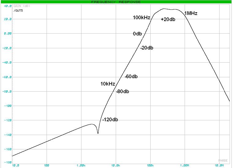
Just "honing" the simulation now - it uses five series connected active filters, I think some of the small capacitors will be eliminated by the capacitance on the IC socket, but its effectively a chain of bandpass filters with 0db @70k and 1.8MHz, -80db @ 10kHz and 10MHz, and >20db <30db between 100kHz and 1MHz..
But I have this nagging doubt.. Am I missing something? This just seems too simple!
Fred.
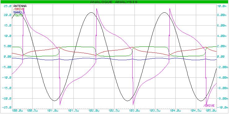
Frequency plot of amplifier stage - Note this is one of the areas where simulators give a far neater output plat than what one gets in reality! ;-) I would be surprised to get better than +10db and expect the floor to be about -90db at best.
Using this amplifier in the oscillator in simulation SEEMS to eliminate all interference from common sources. (I connected a 250V AC dirty mains signal to the antenna via 1M-10pF, and it seemsed to be unnafected - when ive done this on other simulations I can certainly see an effect! ;-)
From: Eastleigh, Hampshire, U.K. ................................... Fred Mundell. ................................... Electronics Engineer. (Primarily Analogue) .. CV Synths 1974-1980 .. Theremin developer 2007 to present .. soon to be Developing / Trading as WaveCrafter.com . ...................................
Joined: 12/7/2007
Heres my OTT simulations - No fine tuning or elegance here at all ;-) -
WARNING! - Purely hypothetical - There may be gross instability if built as a real circuit.
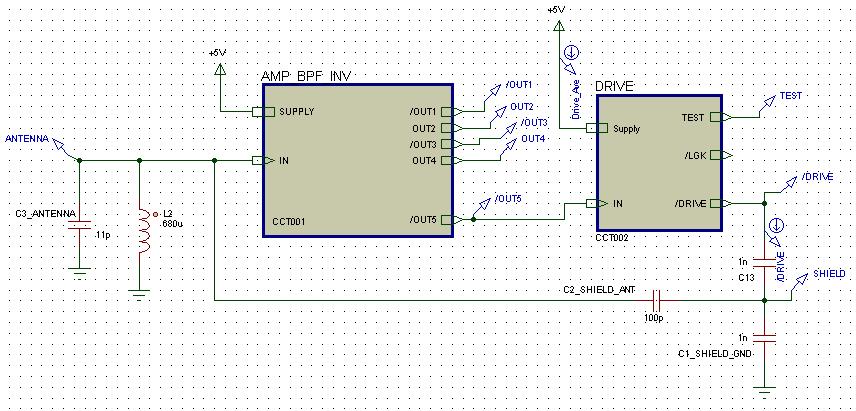
The above diagram shows the two main blocks (BPF/Amplifier and Drive stage) with their coupling components to form an oscillator - Note OUT1 is deliberately low gain so that an analogue buffered sine can be picked up - Other pre-final outputs arent used (but could be to select progressively more distorted sines for wave-shaping) and are there primarily for test probing.
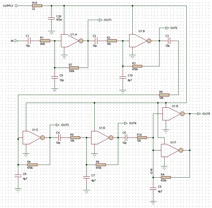
Above shows the amplifier / BPF implementing the reaponse in the last post. My analogue model of the 74HCU04 (Unbuffered CMOS inverters) is used to simulate these parts in linear mode. The capacitors from the inputs of these inverters to ground may not be needed - I cannot remember if I included pin capacitance when I created the model (I think I did) - but these capacitances mainly determine the HF roll-off and probably arent critical unless too big!
It should also be noted that individual feedback resistors actually give gains in excess of the gain available from the CMOS - they are required though for DC biasing the inputs.. Simulation with these parts is difficult because whilst I can simulate the oscillator function with accuracy, simulating frequency response is (probably much) less accurate as the excitation signal must be reduced to keep the CMOS in its linear operation. It is therefore highly likely that the whole amplifier / BPF will need complete redesign and quite possible that an LC BPF following the first amplifier stage would be the best topology.
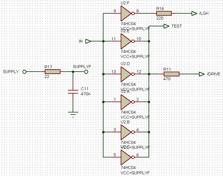
Above = The drive stage
Antenna amplitude can be greatly increased (to 100V P-P) by reducing the value of R11 (down to 220 easily) - Drive current increases proportionally though.
Interesting Fred! The use of multiple cascaded BPFs can add up to a whole lot of rejection. I've been avoiding too much filtering in the loop for phase shift reasons - one wants the LC to resonate as near as possible to the peak to get the highest Q and tank swing, and to minimize operating point dependence on external RCs and such, but if done carefully (and with simple constructs as you employ) I suspect it would work and give great results. I wonder: would locating the BPFs instead at the oscillator output (feeding whatever the next stage might be and not as part of the oscillator feedback loop) give somewhat equivalent behavior?
Though having additional RCs in circuit and with some influence over phase shift does give one the opportunity to do some tempco there.
Hand made capacitors seem rather unlike hand wound inductors (where one can easily do much better than almost anything one can buy in terms of temperature dependence, Q, self-capacitance, etc.). The hair-raising temperature dependent capacitance measurement of the otherwise innocent seeming UHF connector has me a bit gun shy of incorporating a physically manifested capacitance anywhere near the oscillator.
From: Eastleigh, Hampshire, U.K. ................................... Fred Mundell. ................................... Electronics Engineer. (Primarily Analogue) .. CV Synths 1974-1980 .. Theremin developer 2007 to present .. soon to be Developing / Trading as WaveCrafter.com . ...................................
Joined: 12/7/2007
" I wonder: would locating the BPFs instead at the oscillator output (feeding whatever the next stage might be and not as part of the oscillator feedback loop) give somewhat equivalent behavior?" - Dewster
I dont see that it could - With my head still in this TX/RX paradigm, this would be like cleaning up the quality of the TX signal .. Doing this isnt going to improve the recievers selectivity.
I can see that for digital theremin use, the phase issues could be a pain - This is one reason I moved this stuff from your digital thread.. This is really a completely analogue circuit / scheme .. The "inverters" are actually just being used as a couple of FETs, a cheap way to get 36+ matched FETS and protection diodes etc.
Oh, BTW - You are rignt about DIY capacitors! ;-)
Fred.
You must be logged in to post a reply. Please log in or register for a new account.