Let's Design and Build a (simple) Analog Theremin!

Posted: 11/16/2014 11:25:06 PM
dewster

From: Northern NJ, USA

Joined: 2/17/2012

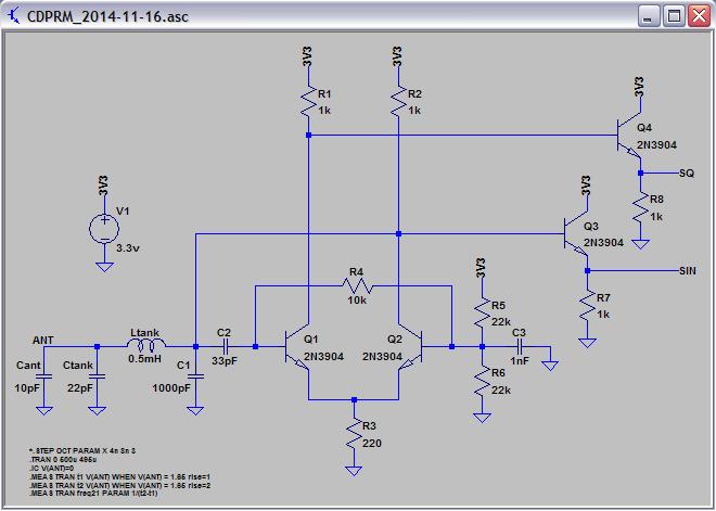
Clapp Differential Pair (ala Robert Moog) : CDPRM

It's an interesting exercise adapting Dr. RM's tried-'n-true EWS differential pair oscillator to the Clapp tank:

80Vp-p at the antenna, two useful waveform options on tap (says the sim, no hardware testing yet).  Dude was indefatigable when it came to circuits, this one seems pretty nice (on paper).  Hmm...

LTSpice file:  http://www.mediafire.com/download/7cb9wbbinc6gbmk/CDPRM_2014-11-16.asc

[EDIT] Just benched a slightly modified version of it (added 47 ohm base resistors).  Had to increase R3 to 470 ohms and lower C1 to 470pF and C2 to 22pF to get it to oscillate, and it's a drift monster.  Tried a constant current source in place of R3 which helps oscillation a bit, but it looks like no dice.  A real shame because it offers so much.

Posted: 11/19/2014 1:05:49 AM
xtheremin8

From: züriCH

Joined: 3/15/2014

ahh,lovely,  it looked so promising on the screen. frankly, one oscillator before the above, i thought it will end in a transistor overkill. merde, why do oscillators drift anyway? i think the heat in the parts is one factor. but  it also must be some sort of feedback, like looking  in a mirror with a mirror behind you. alice in electronicland. i'm drifting too.... anyway, my breadboard art is pretty useless, just too fumblee for my hands, so i can't tell.  it seems like  i'll could do it with a good reading, then.  while strolling in the tw-archive of previous thoughts on theremins, i like this one very much: circuits scratchpad . not sure wich part of it i like most ,just all, but juans hartley-explanations are impressiv. (about page 12,13) 

@dewster: how do your previous described coils look like? just to get the picture.


Posted: 11/19/2014 4:53:09 AM
dewster

From: Northern NJ, USA

Joined: 2/17/2012

"why do oscillators drift anyway? i think the heat in the parts is one factor. but  it also must be some sort of feedback, like looking  in a mirror with a mirror behind you."  - xtheremin8

Lots of things, mostly heating of transistor junctions moving things around.  Two transistors are kind of asking for it if you're not careful as they drift differently.  Two transistors generally introduce more delay, and thermally dependent delay is drift.  There is also phase noise and flutter (low frequency phase noise) which can come from larger valued resistors and transistors.  Delay is the real killer, and the reason for most oscillators not to work IMO.  Non inverting configurations like common base and emitter follower are the safest bets because they are inherently high speed.  Try to use the collector or inversion and it all tends to go to hell.

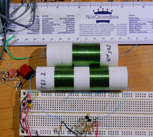
"how do your previous described coils look like? just to get the picture."  - xtheremin8

Above are my two smaller wound coils.  Top is a 0.505mH single layer.  Bottom is also single layer, but the windings are counter-wound and separated ~18mm so destructive coupling is only a few percent at most.  Total inductance is 0.5822 mH.  These are on PVC schedule 40 pipe and covered in clear nail polish, the connecting leads are wire wrap wire.

The oscillator on the breadboard is a BJT common base Clapp utilizing a Darlington configuration to decrease loading and increase Q.  It actually works pretty good but the amplitude is kind of low with a 22pF tank capacitor.  About half of the things I'm trying out lately start up first try, or do so after a bit of fiddling.

Posted: 11/21/2014 4:20:09 AM
Alesandro

From: Russia, The city of three revolutions

Joined: 4/20/2013

What's about your coil winding equipment?

Posted: 11/21/2014 4:23:33 PM
dewster

From: Northern NJ, USA

Joined: 2/17/2012

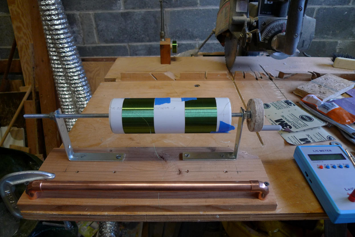
"What's about your coil winding equipment?"  - Alesandro

Above is my cave man winder made from scraps I had in the garage.  The wire comes from the spool in the back, goes under the copper pipe in the front, and then up to the coil which allows one to best see what's going on at the point where the wire meets the coil former.  I use my left index finger to guide and tension the wire, my right hand to turn the crank.  The pivot on the left is a slot rather than a hole and open on the top.  I'm using knockouts for end caps and wingnuts for quicker assembly / disassembly.  Blue painter's masking tape to hold the wire ends which I remove once I've applied some clear nail polish, and then some clear heat shrink tubing (the thin rather brittle type used to hold batteries together).  Before winding the pipe is cut to length using the radial arm saw, the outside is lightly sanded with fine sand paper, and tiny holes are drilled at the ends of the windings for the wire wrap wire connectors.  This is a much larger coil than I'm using now, and I will likely optimize the winder for smaller coils in the future.

Even big coils like the above only take a few minutes to wind, and they look quite snappy when done.  Single layer air cores like this have a very high Q, very low self-capacitance, and pretty much zero temperature dependence compared to commercial coils, but they tend to be bulky and can easily pick up external magnetic fields if not counter-wound.

Posted: 11/23/2014 8:02:52 AM
Alesandro

From: Russia, The city of three revolutions

Joined: 4/20/2013

Great and simple, looking really nice!

As I wrote, IMO the oscillator frequency issues should be taken  in considerations then start the project, however you just slightly wrote about it (or no at all)... It's apply to stability issues... 

May be two 100 kHz oscillators, in the matter, will give more stable hearing tone then two 1000 kHz oscillators???

For example: "TVox-tour" has 120 kHz oscillators...

Naturally, you will say: "It's too hard for beginners - making coil with 3000 (or comes close...) turns".

But, in the matter, there are beginners and beginners... I know people, who aghast at the very thought of making some equipment for winding, for example...

Posted: 11/23/2014 5:02:21 PM
dewster

From: Northern NJ, USA

Joined: 2/17/2012

"As I wrote, IMO the oscillator frequency issues should be taken  in considerations then start the project, however you just slightly wrote about it (or no at all)... It's apply to stability issues... 

May be two 100 kHz oscillators, in the matter, will give more stable hearing tone then two 1000 kHz oscillators???"  - Alesandro

As I pointed out with the spreadsheet at the start of this thread, the oscillator frequency doesn't seem to matter a lot.  Anything from 100kHz to > 1MHz will likely work the same.  For lower frequency oscillators one picks small capacitance and large inductance to maximize absolute sensitivity, but this gives you big honkering coils if you go air-core.  For higher frequency oscillators one picks somewhat larger capacitance and much smaller inductance, where one could use air-core if desired.  I'm not sure what I'll pick for the inductances, perhaps IF transformers without the build-in capacitor. 

Higher frequencies might make the mixer filtering easier as well.

Posted: 11/23/2014 5:51:05 PM
dewster

From: Northern NJ, USA

Joined: 2/17/2012

"Toy" Oscillators

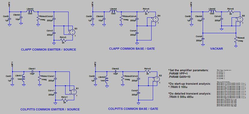
It can be instructive to see things stripped down to the rudiments and play around with such "toys" in Spice.  Below are the various oscillator topologies I'm aware of that employ simple coils and ratiometrically split capacitive voltage dividers in order to generate high antenna voltage swings:

Transistors and their sometimes confusing looking biasing are replaced here with linear voltage controlled voltage sources (VCVS) that have globally set gain and output limit parameters.  The VCVS has differential input and output, with output swing of +/- VPP/2.

For all topologies:

  • Component type and count are the same.
  • Ltank and Ctank largely determine the output frequency.
  • The ratio between Ctank and Csns & Cdrv steps up the antenna voltage (all outputs are roughly +/- 12V with VPP = 1V).

For both the Colpitts and Clapp, the tanks are sensed and driven from the same point, so this is zero phase feedback.  The Colpitts employs a parallel tank so the antenna swing is in phase with sense & drive.  The Clapp employs a CLC pi tank so the antenna swing is 180 degrees out of phase with sense & drive.  With both Colpitts and Clapp, separate capacitors are use for drive and sense, which eliminates the DC lock-up condition associated with same point drive and feedback (and is also a capacitive voltage divider).

The Vackar also employs a CLC pi tank, but here the 180 degree phase difference is actively employed via a capacitive voltage divider as feedback, with the VCVS providing the remaining 180 degree phase difference.

For the Colpitts, the antenna capacitance forms a voltage divider with the tank capacitor, and this can severely damp oscillation when the antenna is loaded down by touching it.  For the Clapp the antenna capacitance forms a voltage divider with the much larger drive / sense capacitors, so antenna loading is theoretically less of a problem.

Oscillators are amplifiers with the input connected to the output.  Technically, there must be 0 degrees or 360 degrees of delay around the loop and gain of greater than 1 to support oscillation (the Barkhausen_stability  criterion).  The Clapp and Vackar need a VCVS gain > 1.5 to function, the Colpitts works down to a gain of 1.  Larger gains (say 10 or more) don't appreciably change oscillatory behavior.

LTSpice: http://www.mediafire.com/download/nmayc2v91s6bew1/toy_oscillators_2014-11-22.asc

Posted: 11/24/2014 1:21:54 PM
FredM

From: Eastleigh, Hampshire, U.K. ................................... Fred Mundell. ................................... Electronics Engineer. (Primarily Analogue) .. CV Synths 1974-1980 .. Theremin developer 2007 to present .. soon to be Developing / Trading as WaveCrafter.com . ...................................

Joined: 12/7/2007

Hi Dewster,

I just have this uneasy feeling that something is wrong (or that I am being an idiot ;-) but I really cannot see the "As I pointed out with the spreadsheet at the start of this thread, the oscillator frequency doesn't seem to matter a lot.  Anything from 100kHz to > 1MHz will likely work the same."

As I see it, the higher the oscillator frequency, the more sensitive it will be to capacitance change - whether at the "antenna" or at the "tank". (well actually, "sensitivity" perhaps doesnt change, but the difference frequency as a function of % does increase as frequency increases)

Take the following "tankless" examples, assume a 10pF antenna capacitance, and a 1pf change:

40.528mH  10pF = 250kHz ; 40.528mH  11pF = 238.37kHz = 11.63kHz / pF.

Vs:

2.533mH 10pF = 1MHz ; 2.533mH 11pF = 953.47kHz; = 46.53kHz/pf

Or as per your above:

500uH 32pF = 1.2582MHz ; 500uH 33pF = 1.239MHz ;= 19.2kHz/pF


As I see it, in order to get a usable difference frequency span (<5kHz, ~3kHz) one must (if using such sensitive oscillators) actively reduce the sensitivity - an extremely thin antenna for example, or by adding capacitance to the antenna (which has the effect of loading the oscillator which in turn means greater drive current is required if good antenna voltage is to be maintained).

It just seems to me that starting with a lower frequency is moving in a better direction for an analogue heterodyning theremin, and that simulations which do not take the required reduction in sensitivity into account MIGHT be misleading..

But I could well be completely wrong - I dont have a clue about your thinking with regards to sensitivity and linearity.

I can see that high sensitivity / high frequency oscillators are ideal for digital or CV generating front-ends - having a offset of say 20kHz with 50kHz for example - and I am kind of hoping you have found a way of exploiting this in some clever way for producing audio frequency difference...

I wish I didnt have this worry - because apart from this, your designs are beautiful - and for all my doubt, the mixer was superb and operation at 3.3V does make great practical sense as one can buy a 5V wall-wart for peanuts and have a 3v3 regulator on boards..

Real nice little tutorial on oscillator types also! ;-)

Fred.
 

Posted: 11/24/2014 5:00:44 PM
Alesandro

From: Russia, The city of three revolutions

Joined: 4/20/2013

Fred, you are right - more frequency, more sensitivity!..

You must be logged in to post a reply. Please log in or register for a new account.