The Ethervox MIDI theremin had 14-but MIDI control messages, and portamento sounded pretty great with it. The problem was that almost no MIDI sound modules could accept 14-bit messages and would fall back to 7-but mode, giving you a pipipipipi kind of sound.
Let's Design and Build a (simple) Analog Theremin!
"Eliminating R10 kills heterodyning in the simulation. The small capacitor didn't seem to do anything," - Dewster
This is because of Q5 in your circuit is coming into saturation. Too large input signal. You lost all the advantages of active mixer!
I played your schematic and found some solutions:
- extending power supply (not suitable, just for illustration, 5 Vpp output)
- input dividers (1 Vpp output):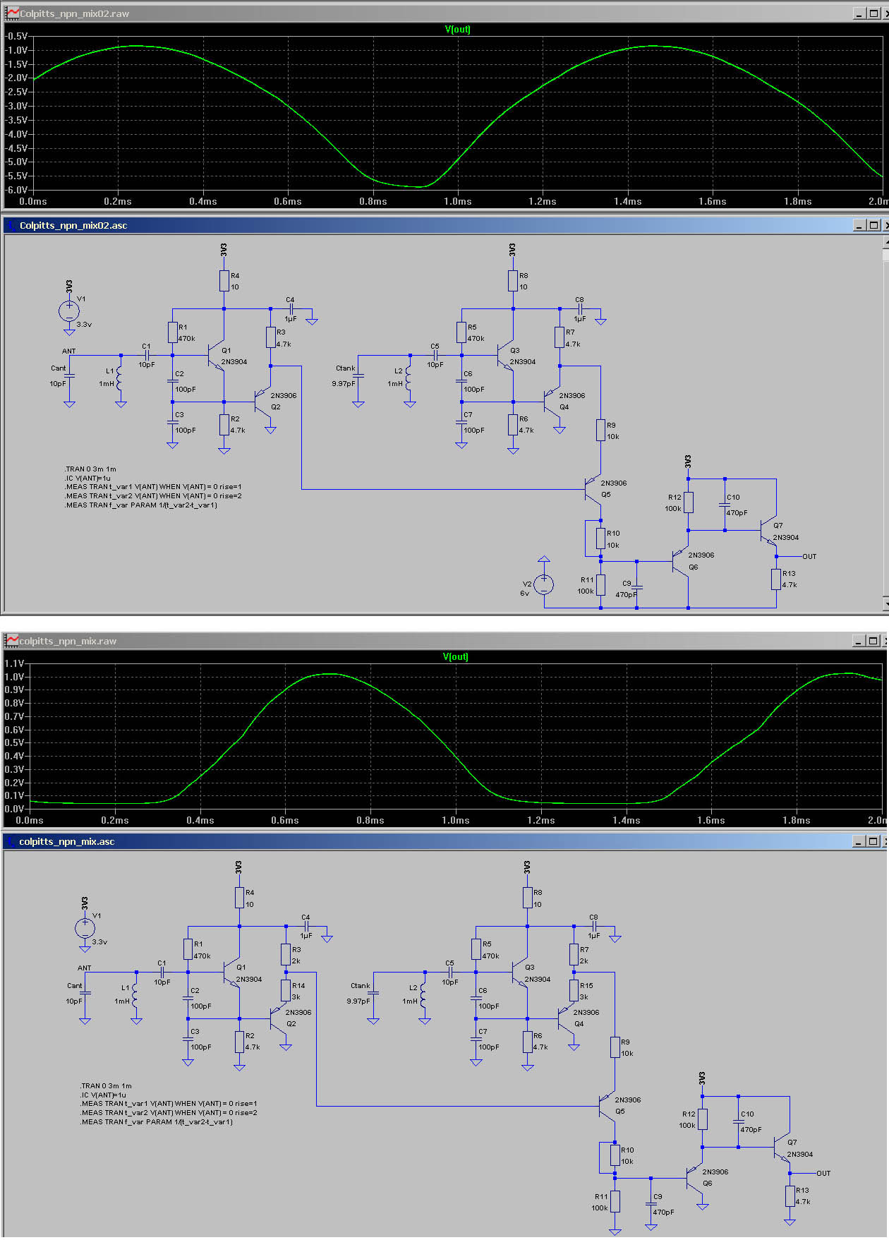
- lowering resistance of R11 (0.5 Vpp output):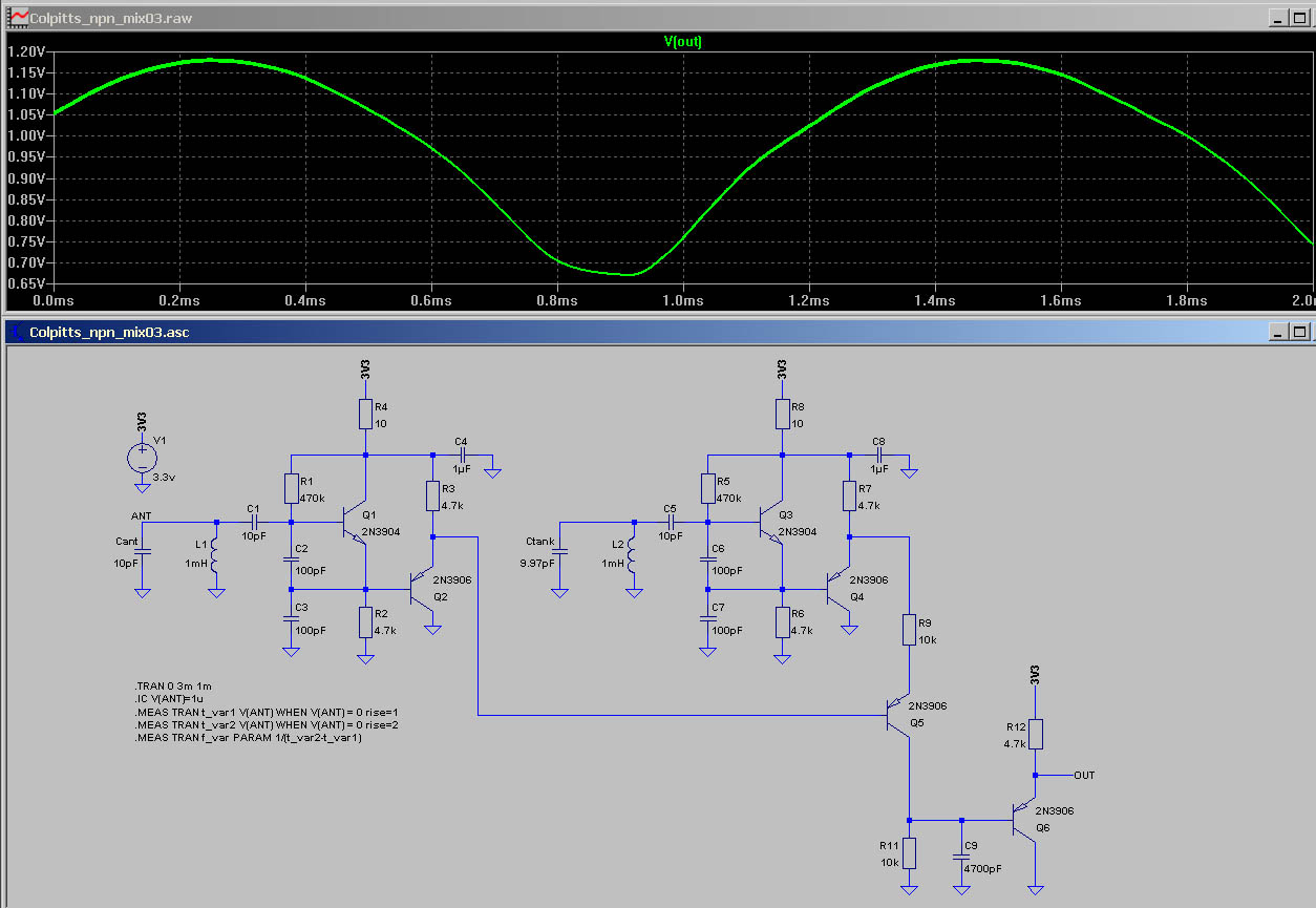
Interesting ILYA. I modded the sim to match your last one and it crapped out if I lowered the heterodyning frequency. I didn't look at it super closely, but when Q5 becomes unbiased by the local oscillator then Q2 likely "sees" R11|C9 through the CB diode of Q5?
A 10k at the base of Q5 fixes things, and I upped C2, C3 and C6, C7 to give a larger voltage swing at the antenna (in sim). I also beefed up the tank and antenna capacitors to come closer to the operating point of the Thierrymin, which required doubling C9 and C10 to get rid of the "fuzz". Who knows if this will even work in real life as I haven't benched it at all.
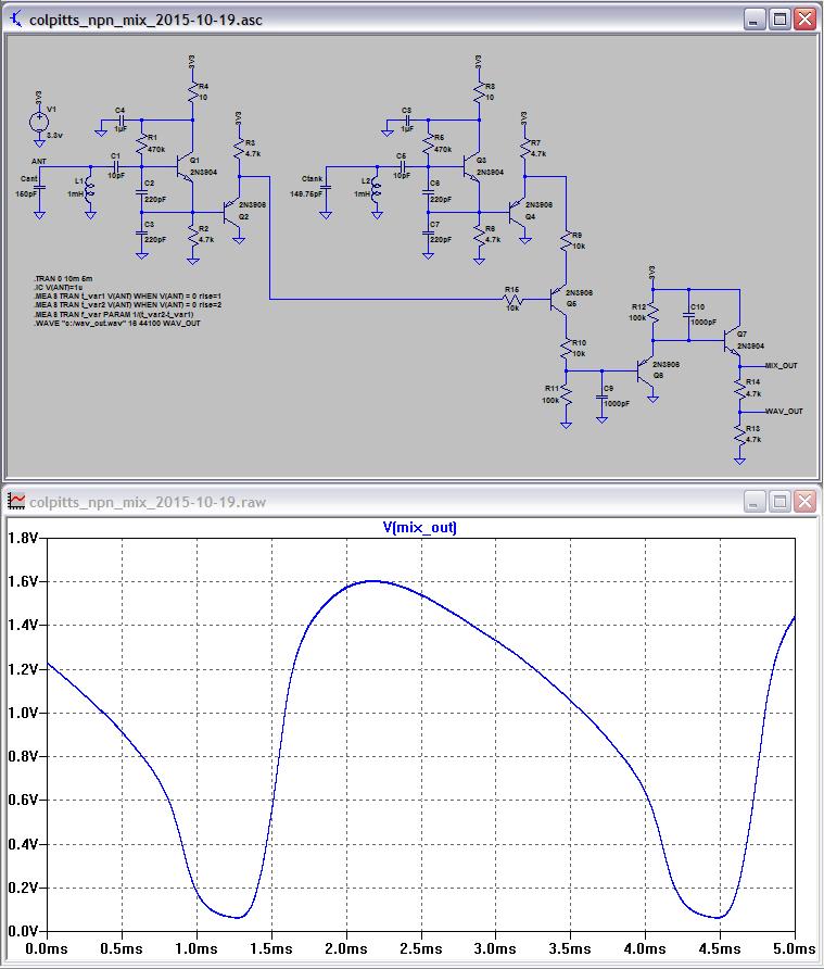
mp3 (@ 312.7Hz)
Colpitts With Separate Stimulus & Sense
It struck me last night that drive and sense might be separated in a Colpitts oscillator:
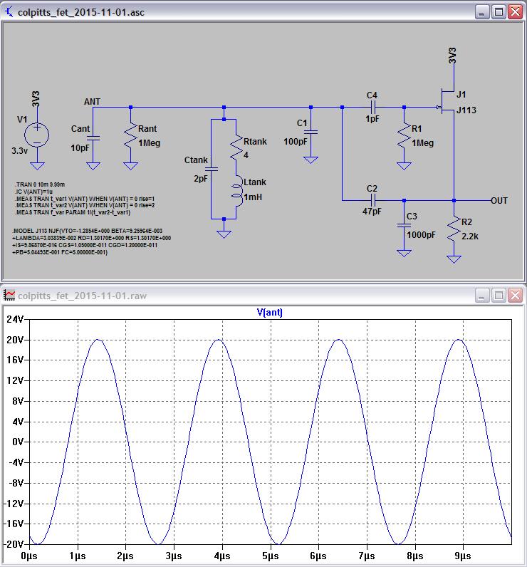
Above C2 provides drive and C4 provides sensing. For higher frequencies and sensitivities C1 can be reduced or eliminated and C2 could perhaps be reduced a bit. For lower frequencies C1 can be increased and R2 decreased to provide more drive current. It's currently running on the bench with a 250uH inductor and no C1, which gives 1.25MHz and ~50Vp-p at the antenna. It looks really stable on the 16.67ms delayed scope. Current draw is ~1mA. I noticed lowering C2 to 22pF made it difficult to initially start. Touching the antenna stalls it but it starts back up again.
I haven't tried it physically, but an NPN won't work in place of the FET in the sim. I believe this is due to the way a FET is a voltage controlled current source, which makes the current drive through C3 and resulting voltage across C3 in phase with the sense voltage.
Spice file here: http://www.mediafire.com/download/a5gblb1v5o1m0lr/colpitts_fet_2015-11-01.asc
Another Mixer
Taking a micro break from math algorithms, doodling with active mixer circuits in LTSpice (what I do for relaxation). This one is interesting:
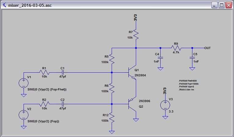
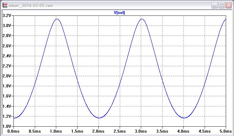
Gives ~2Vp-p sine-ish out with similar input. There is some coupling between the inputs so buffering would be needed before it (assuming you don't want coupling). Playing with R6 gives different waveforms but messes with the output amplitude too.
Spice file here: http://www.mediafire.com/download/17j7vg72w0prm4m/mixer_2016-03-05.asc
[EDIT] Playing with it more, you can simply use two NPN transistors. With R6 & R12 = 47k the output waveform is "pointier" at the top and somewhat skewed. Nice thing about this circuit is it cranks out pretty much the same waveform all the way to DC.
Waveshaping via Mixer
As I noted in the edit above, two NPN transistors work pretty well (in simulation). And by altering the bias / feedback you can alter the output waveform:
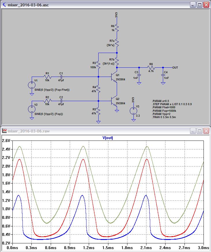
R7 is a 5k pot set to 10%, 50%, and 90% rotation, with all three plotted here via the .STEP Spice command.
Spice file here: http://www.mediafire.com/download/9jl0b29hi0cjtxs/mixer_2016-03-06.asc
I wonder if anyone has done volume control by varying the bias into an active mixer? And I don't mean via 2 or 4 quadrant mixer IC DC input offset.
In general, if the waveform were a square with the duty cycle set to a fixed PWM for harmonic selection, amplitude control might be really straightforward because non-linear circuits wouldn't be able to alter it much.
Hi everyone...i am new to this forum. Actually i was afraid though that unless it is really a very simple problem then I’m not going to be able to have much of a positive input into this project as my level of electronic knowledge is low-albeit significantly more increased since I started looking into theremins.These seem to be pretty accessible constructions for beginners except the custom wound inductors.
Welcome DalDames! Theremins are a great way to explore a variety of electronic avenues. Even though I have an MSEE and electronics has been a serious lifetime hobby, I didn't know very much about inductance or intrinsic capacitance or heterodyning until I got into Theremins.
If you don't want to wind your own inductors (It's pretty trivial, even hand winding without a jig is likely doable, though jigs are simple to make and worth it IMO) you can substitute radio chokes and the like.
A couple of parts on sale at Electric Goldmine that might interest Theremin builders:
http://www.goldmine-elec-products.com/prodinfo.asp?number=G22040
http://www.goldmine-elec-products.com/prodinfo.asp?number=G21807
First is a three terminal 350V gas discharge device, 10 for $3 USD.
Second is a 0 to 8pF panel mount variable trimmer cap, 3 for $2.50 USD.
Dewster,
Is there a simulation program you can input a waveform like this and hear the sound?
Or create a .WAV file from and then play that.
Rich
With ngspice, you can use the spice-audio-tools
It may or may not work with other spice simulators.
You must be logged in to post a reply. Please log in or register for a new account.


