

Let's Design and Build a (simple) Analog Theremin!


I would like to recall one of the simple ideas of timbre formation in simple theremin schemes. I tried different circuits of theremin generators, and simple mixers on ordinary common-use transistors are suitable for any of them. For example BC547 and the like.
If the generators are on field-effect transistors, then such a mixer works, it seems to me, no worse than on field-effect transistors. But it also has the potential for tone control. Therefore, I decided to remind the designers of this idea.
Since in the theremin a big task is to create a rich, rich, beautiful sound. And any ideas of shaping the timbre are important.


Buffered Oscillator
Another oscillator that simulates well, haven't benched it (yet):
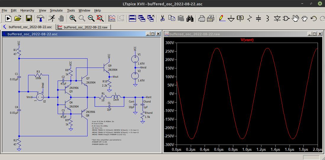
Uses my standard buffer for drive and sensing via the power rails, and something like a single CMOS inverter for some gain. I like this approach because it somewhat isolates the CMOS I/O from the coil. The bipolar supply simplifies the inverter model, and wouldn't exist in the real circuit.
LTSpice file here: https://www.mediafire.com/file/d26llr2gyaicfgr/buffered_osc_2022-08-22.asc/file
[EDIT] It's pretty much crap on the bench, barely oscillates no matter what I do.

Uses my standard buffer for drive and sensing via the power rails, and something like a single CMOS inverter for some gain. I like this approach because it somewhat isolates the CMOS I/O from the coil. The bipolar supply simplifies the inverter model, and wouldn't exist in the real circuit.
Interesting.
lvc1gu04 is simulates ok here.

On the subject of PCBs for coil testing: I designed a 1-layer board that can be configured to test 1-2mH of inductance from SMT components. But, it can also be bypassed or depopulated to test an air coil or through-hole part.


It was designed specifically with the D-Lev in mind, but I think it could be adapted relatively easily to anything else. It's mostly a mechanical breakout. But the internally threaded, solder-down M4 standoffs let you screw in a rod or plate as desired, and to use them purely as mechanical mounting points, nylon washers can be added or the cut-solder jumpers can be cut.
Instinctively I'm a bit wary of the use of unshielded wires to go between different parts of the circuit, so I designed around a shielded u.FL connector. But I doubt those can handle the voltages at play here so I'll probably switch to BNC.
I'm also realizing that at the swing voltages here arcing might be a problem.
In any case, does this board seem useful? If so, I'm happy to panelize it into my next order, I have a few others in the pipeline.

Ekahn,
My knowledge is fading in my old age but I believe you’re L1 & L2 are too close together to get the performance you might be after, you do not want them to inductively interact. Did you bench test your approach, more distance is better 3” to 5” ?
Christopher
Ekahn,My knowledge is fading in my old age but I believe your L1 & L2 are too close together to get the performance you might be after, you do not want them to inductively interact. Did you bench test your approach, more distance is better 3” to 5” ?Christopher
Good catch, thanks. I think this (or something like it) will eventually make its way into a large plate antenna, so the mounting holes and the coils will be spaced further apart.
You must be logged in to post a reply. Please log in or register for a new account.