Mixer and voltage controller amplifier. OTA approach.
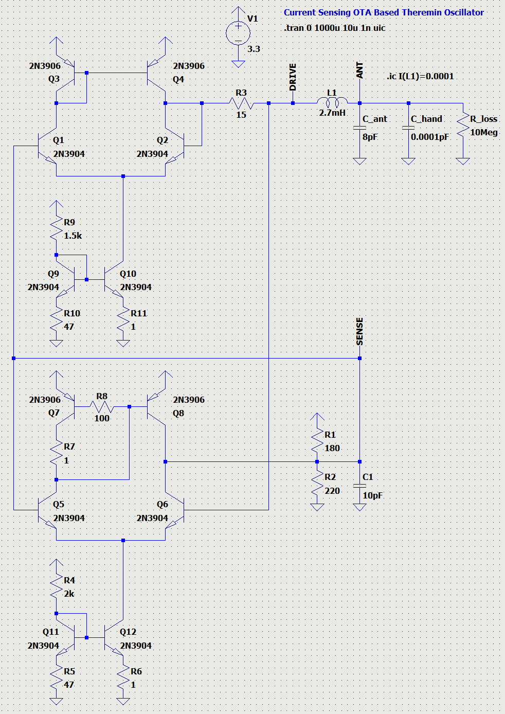
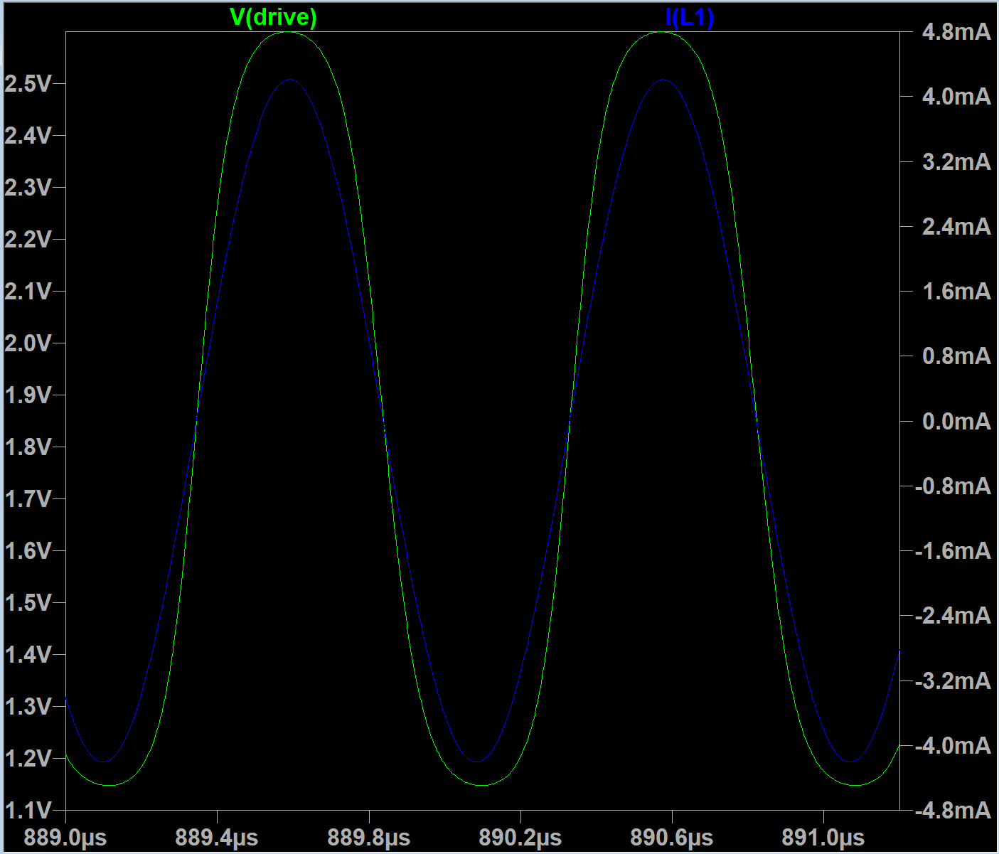
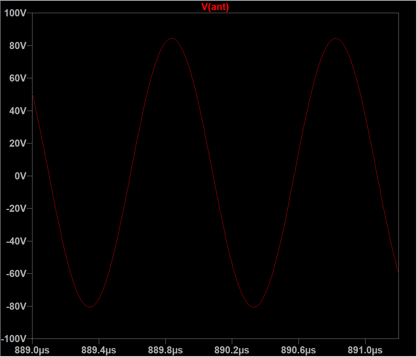
After playing with OTA (operational transconductance amplifier) as theremin output buffer with current sensing (see this post in wallin oscillator thread),
I've designed not very simple, but high quality analog mixer (multiplier) for analog theremin.
LTSpice model: github link

For two pure sine 1 Vpp input signals near 1MHz with 1KHz difference, output signal 1 Vpp has low harmonics level for both low frequency (2,3,4 KHz) and high frequency (1,2,3... MHz) are about 57dB.
Differential amplifier with current output on Q1..Q6 which amplifies input signal IN1 is controlled by voltage to current converter on Q7, R9 - by voltage from input IN2.
Output current is being filtered (integrated) by C1 to get rid of RF frequencies in output.
This mixer is powered from 3.3V
To work from different voltages, some tuning may be required (R9, C1).
Input voltage ranges may be changed from 1 Vpp (up to 1.5Vpp for IN1 and 2.5Vpp for IN2) or lower values, but may require changing of bias points using R3-R8.
Output voltage range is tuned to be 1V p-p, centered at VCC/2 (1.65V), but it can be changed by R1, R2, C1.
Supports input frequencies in a wide range: works fine with 10Mhz and 100KHz (but on lower frequencies, RF LP filter passes more high frequency to output.)
Inputs: 1Vpp 1Mhz and 1.001MHz
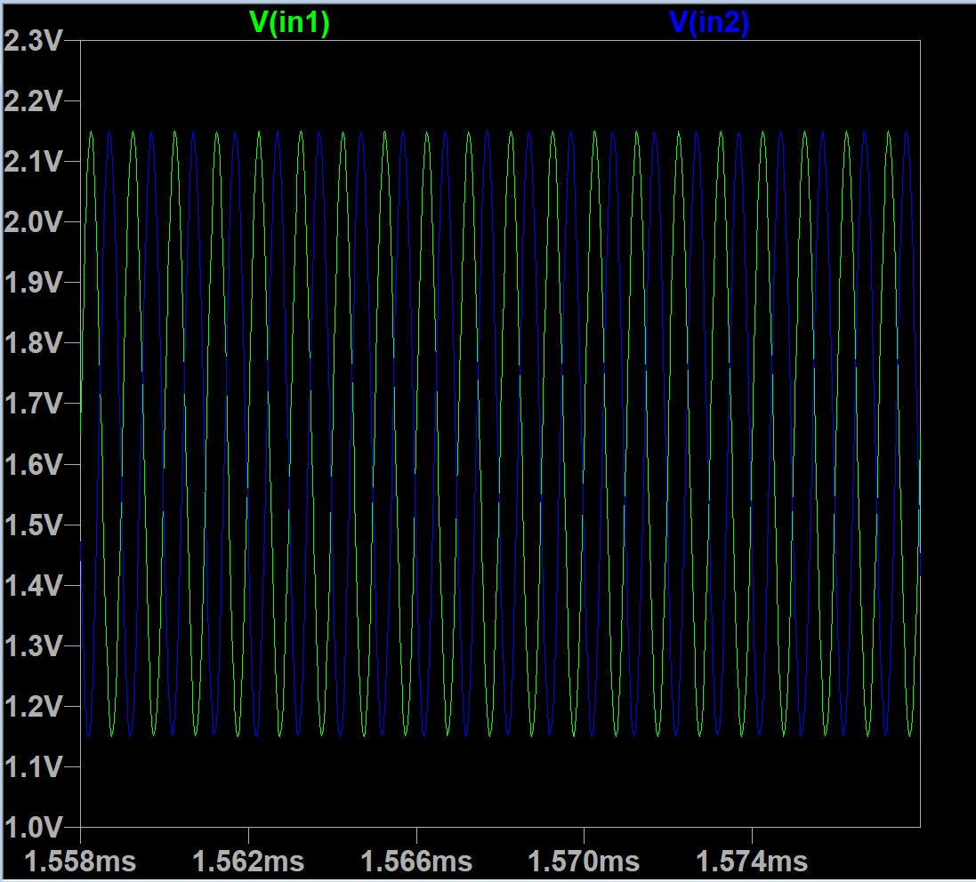
Output: 1001KHz - 1000KHz = 1KHz
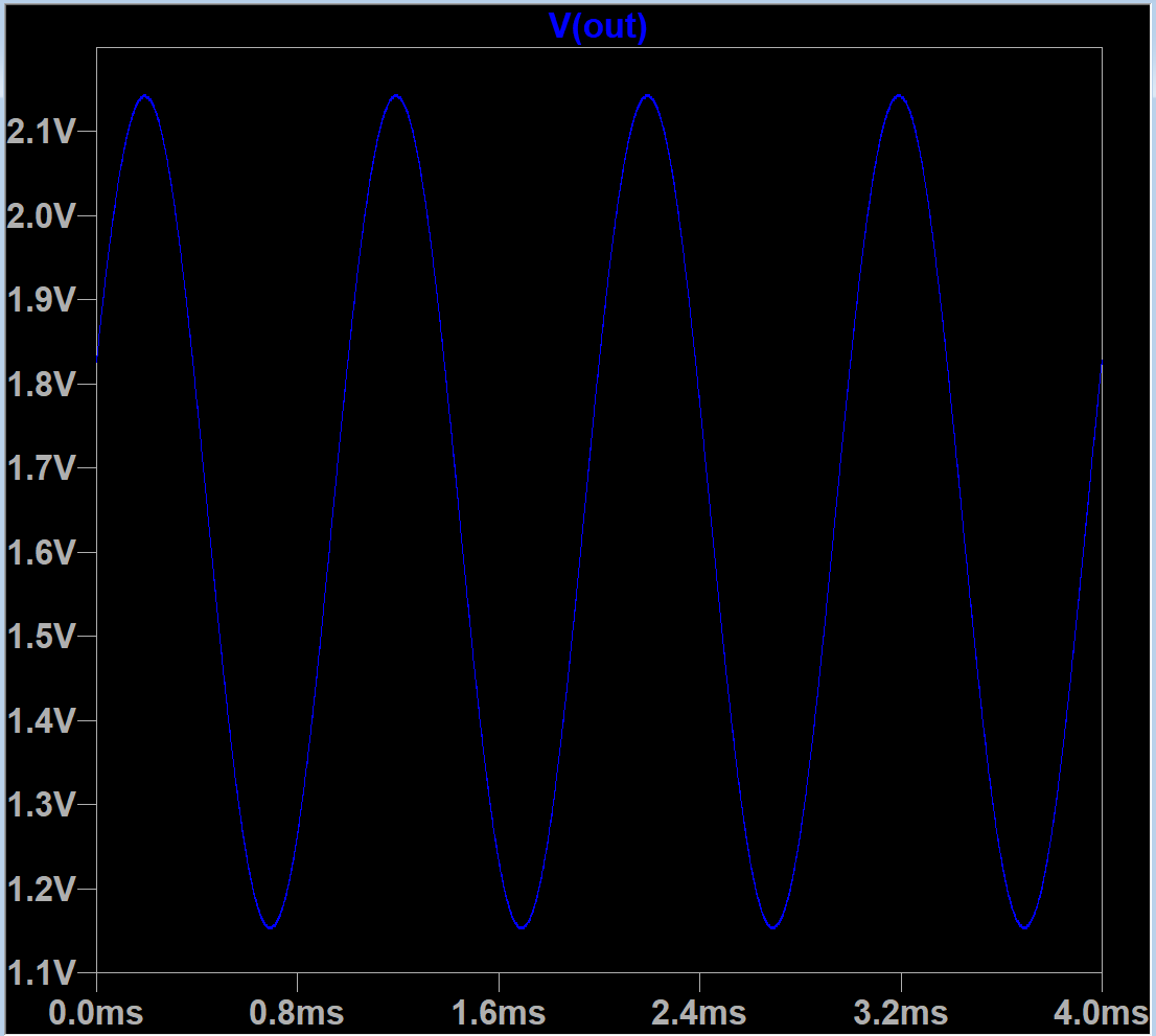
Of course, pure sine output is not the best waveform for theremin, but it may be turned into non-sine by changing of one of or both inputs from sine to some more interesting sounding wave.
As well, some distortion / shaping stage may be added after mixer input.
Similar approach with additional OTA stage can be used to add VCA for volume control.
Moreover, this schematic may be used as is to work as VCA - with output of mixer fed to IN1, and volume control voltage - on IN2 input.
Let's try...
LTSpice model: github link

Volume control is logscale below 1.4V and almost linear for higher voltages. By choosing of voltage control working input range, it's possible to change linearity.
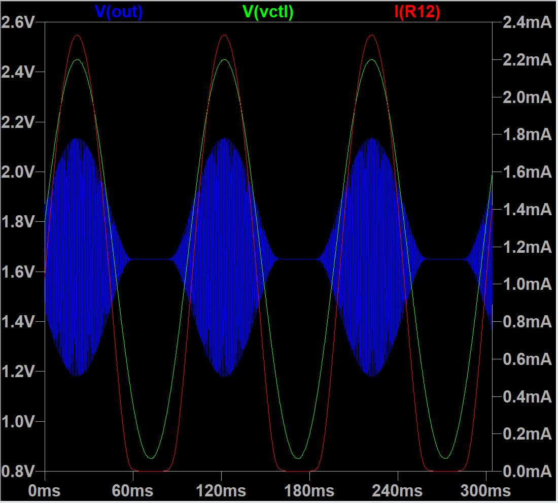
This schematic can be tuned for different waveforms - between pure sine and almost square by changing of diff cascade overload.
I think, waveform shaping can be made adjustable - by placing pot somewhere.
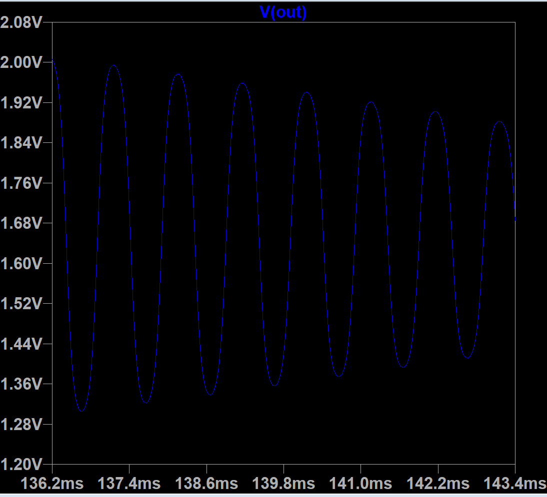
Second stage amplifier filters out RF even more, giving clean signal.
This schematic is big enough (14 BJTs). But transistors are cheap now, so it should be inexpensive.
As well, we can try to use OTA ICs (e.g. LM13700 NE5517 OPA615 OPA860 OPA861), but all of them cannot be driven by 3.3V instead of discrete BJTs, and they are more expensive.
TBD:
- design "mixer" to generate volume control voltage from volume fixed and variable oscillator signals. Can it be done on OTA?
- design good OTA based current sensing oscillator for theremin (VFO)
- design good and stable "fixed" frequency oscillator which can be slightly adjusted with a pot (can it be done w/o varistors?)
- design some waveform shaper with pots control to make sound more interesting
- combine all listed above togeher to make an analog theremin
P.S: Is pitch antenna linearity a real problem?


