basic experiments

Posted: 7/7/2016 10:04:08 PM
oldtemecula

From: 60 Miles North of San Diego, CA

Joined: 10/1/2014

dew, D1 & D2 have no forward bias so no audio will develop. 

As soon as C3 or C6 charge up there is no current flow? The diodes need a parallel 100k resistor, cap bleed off or minimum micro-amp dc forward current from somewhere. I can not emphasize enough the importance of controlled mixer diode bias, most think anything works, that is why they are led astray over the years. This is the point of conception, the mystery is why is it not obvious?

Christopher

Posted: 7/7/2016 10:45:01 PM
dewster

From: Northern NJ, USA

Joined: 2/17/2012

Oops, you're right Christopher, for some reason I completely missed C3 & C6.

In simulation often something will seem to work from time zero, and it certainly may for a microsecond or a millisecond or whatever, only to die if given sufficient time.  One runs into this kind of thing all the time and particularly with HV oscillators, where the initial conditions may stimulate the tank and make it ring for a while.  I've learned the hard way to let the sim run a long time before recording results, and to examine really long-term sims for decay activity.  The oscillator that seems perfect in the short term may not oscillate at all given a bit more time.

Posted: 7/10/2016 4:53:23 PM
JPascal

From: Berlin Germany

Joined: 4/27/2016

Oh, if we are cousins, when did you move from germany, Christopher? Kann ich dich auch auf deutsch ansprechen? wink

Now to the manifold textlines above, after my last posting. Sorry, I really do not believe that you have any doubt that the circuit is functionable and the simulation too. If you have questions to me, I will answer them as soon and as good as possible. 

There is no need for both, a biasing the diodes and/or an additional parallel resistor. The serial condensers works in a proper manner to separate DC from rf mixing signal. You can bypass them ore not, but then we discuss another circuit with another voltages, not mine. The three audio signals I have shown you can measure in practice. No artefacts from program, time range for simulations is long enough, all is very clear and in function like wished. Rest of rf signals can of course rather be smoothed, I show them her for knowledge.


Posted: 7/10/2016 6:04:49 PM
oldtemecula

From: 60 Miles North of San Diego, CA

Joined: 10/1/2014

JPascal, Meine Großeltern Deutsch gesprochen, nicht von mir.

I understand electronics and value most opinions of dewster, but not always.  laughing

You have made some electronic comments that make me wonder if you are an engineer?

I am not an engineer and do not trust modeling theremin circuits, you may be validating this point for me.

Christopher 

Posted: 7/10/2016 8:20:14 PM
dewster

From: Northern NJ, USA

Joined: 2/17/2012

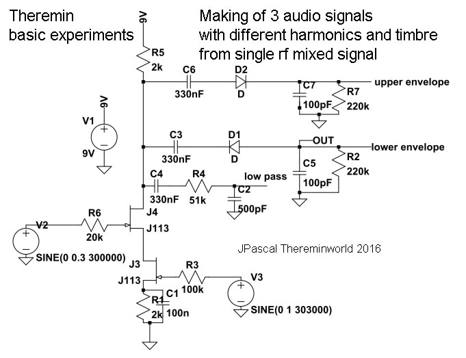
JPascal, a diode and capacitor in series without anything connected to the intersection is almost guaranteed not to do what you want it to do. The capacitor will charge up and eventually no significant current will flow.

Take the upper path: R5, C6, D2, C7, R7.  The RC time constant here is dominated by C6 and R7, and 300nF * 220k = 0.726s, so your simulation would have to run for a significant fraction of a second before you see the effect.  I believe your sim is only running for 1ms?

The LTSpice directive I might use here is:

  .TRAN 0 500m 499m

This lets the sim run for 500ms but only starts recording data to display 1ms before the end.  To see the charging in action just remove the 499m from the end of the directive.

It also helps to reduce huge capacitor values somewhat so you don't waste so much of your own time letting them charge up in simulation.  You can also set initial voltages for capacitors and inductors in Spice.

You should also define your diodes as 1n914 or similar rather than rely on the default.

Posted: 7/13/2016 2:49:46 PM
JPascal

From: Berlin Germany

Joined: 4/27/2016

Christopher, thank you for your frank words. Wondering about a thing or some phenomena is the best start to get more knowledge and to find solutions. I am not an engineer. That what we do here is much more a holistic approach and you need experiences in electronics, physics, acoustics, construction, playing an instrument.The liason of physicist Lew Termen and viola artist Rockmore is the best example herefor.

To the technical remarks by Dewster. Indeed there is some potential to enhance the simulations validity. But the path C6 - diode is not limited by the resistor 220k. It is responsible for sufficent discharge the 100 pF capacitor in the blocking period. For the simulation I used 4 to 5 Milliseconds in relation to the time constant from 220k x 110pF. Nevertheless I have stabilized the rf zero line behind C6 with resistor 100k to gnd. To reach a higher voltage of rf signal the 2k drain resitor was replaced by 4k. The result is shown with delay of one second. Now it seems to be a time stable simulation. The diode used may be a universal silicium type. 

Theremin envelopes for different sound

I will add the diode parts in my initial circuit for the pitch control. Three significant different audio signals (like square wave,  sinusoidal, sawtooth shaped) are sufficient for my Theremin. Additionally I can mix them.

The next step is now the volume control and its role for sound effects.

Posted: 7/30/2016 12:21:32 PM
JPascal

From: Berlin Germany

Joined: 4/27/2016

What is my first thought about the volume control? A good Theremin sounds like a string instrument and/or a voice. Why it should not be best played like a violin or a cello? Left hand for pitch and vibrato and right hand for dynamics and volume. But the only virtuoso I found playing the left handed theremin is Pamelia Stickney (Kurstin). Why? She plays until now bass and cello. Google theremin doodle for Clara is also a tribut for left handed theremin, but Clara, the viola artist, did not played volume with the right hand. What else would become otherwise of her, we will never know.wink

Posted: 7/30/2016 1:01:27 PM
dewster

From: Northern NJ, USA

Joined: 2/17/2012

I play guitar so my first inclination is to have pitch on the left and volume on the right (same argument for most fretted and non-fretted stringed instruments).  But pitch is so tricky on a Theremin that I believe the designer should arrange things so pitch is controlled by the side of the body with the best fine motor control (right).  Ideally the physical design would easily allow for both options to accommodate any playing style.

Posted: 8/2/2016 8:21:32 PM
JPascal

From: Berlin Germany

Joined: 4/27/2016

I think it is reasonable that guitar with frets or keybord are kinder to beginners than the violin is. Both hands need thousend ours of training and get fine motoric on progress. I guess a professional violin artist is able to play the pitch with left hand as well as right but has no time wasting due to reprogramming in brain by using a left handed Theremin.

Posted: 11/20/2016 8:43:58 PM
JPascal

From: Berlin Germany

Joined: 4/27/2016

For the volume control I tested a simple but usefull voltage controlled attenuator. About -100 dB are totally enough with respect to the loudness scale from fortissimo to silence. Here is an example circuit with two cascaded jFETs. More attenuation can be obtained with a third additional jFET voltage divider. The following amplifier should be high resistive, e.g. more than 200 kOhm impedance.

The practical results are good.

VC Attenuator  with jFETs VC Attenuator signal reduction

You must be logged in to post a reply. Please log in or register for a new account.