basic experiments

Posted: 3/25/2018 1:56:26 PM
dewster

From: Northern NJ, USA

Joined: 2/17/2012

"There is no need for hundreds of mH"  - JPascal

I completely disagree.  You need a series LC resonance that "fights" the parallel tank LC resonance to influence linearity.  And it can't have significant self-C or it won't work, hence the series combination in the EW.  And the resonant frequencies of both LCs must be very close for it to work.

"With and without coupling C the hand capacitance is also here strong linear to the audio frequency."

Not surprising.  You won't find a linear solution to an exponential problem (it took me forever to realize this).

Also, simulation (Fast Field Solvers FastCap) has shown me that your model of the antenna C and hand C are too simplistic, though the result is fairly close. The antenna intrinsic C isn't static, but changes with hand distance.  Something to think about perhaps if you are taking it all back to first principles.

I believe your exercise is essential for anyone truly interested in analog Theremins, and it's one I probably haven't sufficiently pursued.

Posted: 3/25/2018 5:53:00 PM
JPascal

From: Berlin Germany

Joined: 4/27/2016

Dewster. Maybe this is a mentality, language barrier (my problem) or whatever problem. Ask me in detail and I will try to find an answer. But I feel your comments a little destructive. More than 200 mH for linearization coils and a 10 pF antenna C result in resonances below 113 kHz, what Theremin mean by hundreds of mH?

"Not surpricing". Yes, it is for me of course not a surprice. How many discussions where done about the lineariziation by series C, parallel to antenna C, the great influence of body capacitance? But hand capacitance remains still linear to audio frequency and thus pitch linearity is also unchanged. Only the pitch range and oscillator frequency change.

Is linearization by fighting LC parallel tank resonance against whole series LC resonance true or only a myth? I have to proofe it my way because your data input is not available.

Too simplistic? My goal at all, you got it!! Theremin does not need maxwell equations.

Posted: 3/25/2018 6:09:38 PM
dewster

From: Northern NJ, USA

Joined: 2/17/2012

Sorry, not trying to be destructive, but rather constructive.  You're right, I should have said tens of mH.  The EW uses 4 x 10mH with each having ~5pF max. in parallel, or ~1.25pF max total across a single 40mH.  This is very different than the EQ inductor you are spicing (21pF across 2.2mH which seems like a very poor candidate for EQ inductor).

I'm confused: to show pitch linearity, shouldn't you take real hand & antenna C data and use this as input to your spice simulation, then plot difference frequency on a semi-log axis (as the ear perceives pitch)?

[EDIT] Sorry to give you unsolicited advice, but the fastest way to understand the action of the EQ coil might be to simulate an existing design, rather than making one from scratch.

Also, without the spice file I'm not sure what the "output" is in terms of a transfer function?  Most analog oscillators have some phase error at resonance, and the oscillator functions via feedback and phase shift.  In other words, the antenna signal is only an indirect feedback input to the oscillator.

Posted: 3/27/2018 12:43:11 PM
JPascal

From: Berlin Germany

Joined: 4/27/2016

I am trying to give an interim summary to my above results. This is a little exhausting, hope it is understandable.

1. The hand capacitance is nearly linear to the pitch change of an ordinary theremin, post 72, 74 (a few inches away from the antenna). That is, we just have to look at hand capacitance and distance to solve any pitch linearity problem. Body capacitance and in series C or parallel C to the connected antenna shifts only oscillator frequency and the variable pitch range (post 78, 80).

2. This pitch is - by using rod antenna - nearly proportional to Ah/(d ln(d/r)), so that depends on the area of the hand Ah in front to antenna (conductive surface "seen" by antenna), on the hand distance d and on the radius r of the rod. Length of the rod is not essential here as it is long enough to the hand dimension. See post 72 with the here in TW first published new fomula. (note: in case of a plate condensor or plates as antennas this dependence is approximately proportional to Ah/d.)

3. These dependencies would generally imply the impossibility of obtaining pitch linearity (logarithm of hand capacitance or pitch should be proportional to distance). Therefore, two additional measures are necessary and useful in practice:

a) using the pitch offset function / knob to linearize the low pitch frequencies, see post 61.
b) for the near distance using a proper moving path of hand to the rod, see example in post 64, 66. Alternativ a special antenna design, see example in post 68.

4. Resonance conditiones in a theremin circuit are determined by inductances and capacitances that result in maximum impedances or in conductances, as shown in post 76. The advantage of an EQ coil is, that role of stray and some further additional capacitances from circuit are negligible if the series resonance with antenna at lower frequency is used. (In experimental practice sometimes occures an oscillator frequency jump, this is due to the various possible resonance conditions). Approximation formula to find the right frequency I give in post 76.

(Before I blindly trusted LTSpice I calculated the network in my post 77 step by step in Excel using Kirchhoffs rules and with complex (jX) impedances of all L and C. Results see in post 77. The math steps behind would not be of interest here, I thought, but is not rocket science.)

5. Open task is the "miracle condition" for pitch enhancement and linearization improvement within the pitch range. In a next topic I will try to find an answer.

Posted: 4/11/2018 7:46:45 PM
JPascal

From: Berlin Germany

Joined: 4/27/2016

Let's go to point 5. And thus some results with a typical 30 mH = 3 x 10 mH coil and with low self-capacitance of 2 pF. The tank resonance is chosen at first much higher and than in the range of the serial resonance frequency of the pitch oscillator. In both cases hand capacitance was varied from zero to 1 pF. All calculations by excel. What you can find is that shift by hand capacitance is in the first case higher. In the "double resonance" case splits the serial resonance but both frequencies are shifted lower. So I'd recommand for theremin development the first variant instead the second one.


..............................................................................................................................................


Posted: 4/11/2018 11:06:57 PM
dewster

From: Northern NJ, USA

Joined: 2/17/2012

"Seems like a tuning phenomena but I was never quite sure what was going on."  - oldtemecula / Touchless / RSTheremin / Christopher / etc.

I think I found the problem.  Technical pushback can feel like personal attack.

Lord knows I can whinge with the best of them, but you're all sour grapes these days.  Are all the pokes in the eyes really necessary?  If nothing else, please stop attacking FredM as he's not here to defend himself.

Posted: 4/20/2018 8:36:59 AM
JPascal

From: Berlin Germany

Joined: 4/27/2016

What about stay in track here with basic experiments?

My conclusions until now. I have found, described and proofed a set of formulas with respect to the antenna for the pitch part of theremin. Now I will deal further with the dynamics of the volume part and the basics and principle ways how to get the proper overtone spectras.

Hope there is still remaining interest here despite many others who dealt with it.

Posted: 4/20/2018 1:31:13 PM
dewster

From: Northern NJ, USA

Joined: 2/17/2012

"What about stay in track here with basic experiments?"  - JPascal

So sorry!  This thread interests me very much but I'll stop posting in it.  

And I'll stop replying to Touchless / Christopher / Oldtemecula / RSTheremin as all he's done for the past several years is troll me.  Have a nice life.

Posted: 4/20/2018 3:10:39 PM
JPascal

From: Berlin Germany

Joined: 4/27/2016

"This thread interests me very much..." - dewster That pleases me very much. I don't want anyone to be trolled here.

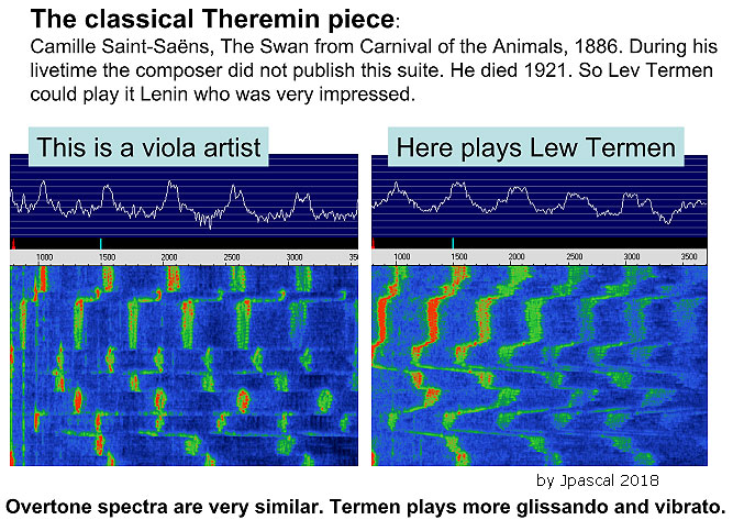
Now to the next. What is the difference if old master Termen about 90 years ago and a young viola artist today are playing their own instruments? What you can see are the frequency spectra and waterfall diagrams for time.

Posted: 5/19/2018 1:03:11 PM
JPascal

From: Berlin Germany

Joined: 4/27/2016

A quick and dirty video shows overtones and audio signals from my experimental circuits. 

To get a sound like an instrument, some conditions are essential.

A - signal shape changes with volume

B - signal shape changes with frequency

C - certain areas of frequency are enhanced (formants)

D - volume control is so dynamic, that "string" or "push" with loudness is possible

E - ...

You must be logged in to post a reply. Please log in or register for a new account.