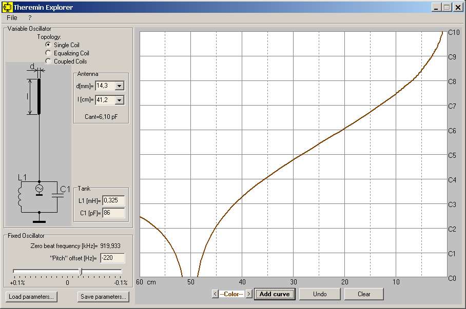
Here comes some results of simulations. The zero point setting at 56 -58 cm is done by variing the offset. Stretching the zero point to higher distances is of course possible.

Now hold your horses there partner, we've been told repeatedly that the Phoenix is "perfectly linear"! So your graph is clearly wrong! 
Interesting how they are all more or less just transposes of each other, even with / without EQ coils and whatnot. This is why I gave up on analog long ago, way before I could do a definitive comparative analysis of existing Theremins.
Coupling of the oscillators can profoundly alter the far field, I'm guessing that's not in your sim?
This cannot exact compare the built theremins. But it can show, that very different oscillator frequencies and inductances are possible with similar linearity correlations. I could now add coupling capacitors, vary the assumed hand front area and so on. The behavior within the curves would not change significantly.
I too am fairly certain that the Phoenix oscillator & spring door antenna form a simple (un-EQ'ed) oscillator, thus producing the pitch response ILYA shows above via his excellent software sim. As such I would expect the usual cramping near the antenna, the usual fall off to zero at null (possibly exacerbated by oscillator coupling), and the usual fairly linear mid-field.
Been playing a bit today with a sim of it, but quite frankly I lost almost all interest in this subject long, long ago, and have no idea why I'm subjecting myself to it yet again, except to re-convince myself that there most likely isn't any there there:
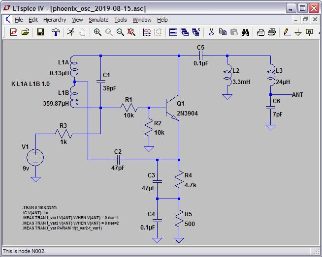
I made no attempt to follow the component numbering in the various schematics / PWB layouts.
I calculated the L1 tank inductances from the turns ratios of the IF transformer (42IF110-RC). It seems to oscillate pretty much the same whether C2 is connected to the tap or the top of the transformer.
L3 & C6 form the approximate spring door antenna L and intrinsic C (L calculated via INCA, ~C given by ILYA).
In LTSpice it oscillates at ~1MHz (stray C would likely lower this some) with +/- 6V peak at the antenna, I have no idea (and almost don't care) what it does in real life.
I may have made a mistake here, or the schematic could be wrong, or the design could just be the way it is, but I think it's somewhat strange that LC tank (sans L2) doesn't have a very low impedance path back to ground (or VCC, same thing in small signal analysis).
Also, clams that L2 to ground solves ESD issues could be dead wrong, a high Q circuit can ring like crazy when hit by ESD, whacking everything around it many times before the energy decays away. One would have to test this in real life to know exactly what happens, but it wouldn't surprise me at all if the inclusion of L2 actually makes ESD hits worse. ESD edges have lots of high frequency content.
If anyone else wants to play around with it in LTSpice, have at it: [LINK]. Though the author will tell you that science and engineering somehow don't apply here.
I do think the tone / timbre of the Phoenix is quite nice.
To be clear, none of this is sniping, sour grapes, etc. on my part. Call me crazy, but fantastic claims need to be backed up by fantastic results with solid explanations. All we've gotten for many, many years now regarding the screen door spring antenna is fantastic claims of linearity, along with a lot of shouting down of those who have the temerity to question those claims or the possible mechanisms behind them.
(Countdown to Christopher spamming my email inbox with tons of porn...)
One crummy video of you demonstrating the linearity via open / closed hand gestures would have gone a long way. How hard is that?
And you shouldn't post people's emails in an open forum without asking permission first.
https://blogs.scientificamerican.com/observations/a-scientist-must-go-where-the-evidence-leads/
Demonstrating Pitch Field Linearity To The Masses
Here is one way to do it that is quite simple, and doesn't require any complicated or expensive equipment or rulers, just a guitar tuner or some other form of pitch display / frequency counter / software:
0. Set up the Theremin so sensitivity is as even as possible throughout the pitch field (like for playing).
1. Place open hand with fingertips ~1cm or so from the antenna, write down pitch #0, close hand, write down pitch #1.
2. Open hand and pull it away from antenna to again get pitch #1, close hand, write down pitch #2.
3. Open hand and pull it away from antenna to again get pitch #2, close hand, write down pitch #3, etc.
Try to keep your body in one fixed position during the testing, only moving your arm and hand, otherwise you will confound the results. Repeat the above steps until your hand is about 1/2 meter from antenna, or until the null point is reached. Publish your data, optionally graph it. Take a video of the process as above and post it to YouTube. To facilitate data logging for the test, you might want to employ the video itself for this, as it allows one to quickly do the test and glean the data later.
Try not to cheat with the open/closed hand gesture! Quickly opening and closing the hand while it is in one position can demonstrate repeatablilty both to yourself and to the viewers (which I demonstrate the video below).
From my video above, if you watch the LED bar graph at the bottom you can see that it corresponds to four consecutive 1/2 notes (there weren't enough LEDs on the FPGA board to support a full octave display) and that it is modulo one octave (i.e. the pattern repeats every octave). Nevertheless, you can clearly observe that the first open/closed hand gesture causes somewhat more than one octave change in pitch, with the following six open/closed hand gestures producing very close to one octave change in pitch, and the final gesture again going non-linear to zero pitch or null with way more than one octave change in pitch (there are in fact infinite octaves to the null point - the scale is logarithmic and so by definition can't include zero).
This early FPGA experiment of mine is equivalent to a simple non-EQ coil type heterodyning analog Theremin, and so demonstrates the surprisingly good linearity of over a large majority of the pitch field for that topology (six ~linear octaves). The reason designers incorporate an EQ coil is to help linearize the pitch near the antenna, and perhaps also to somewhat stretch the octaves out to increase ease of playability. (Besides providing much better linearity than that demonstrated in the above video, the D-Lev provides the user with control over the note distance, and I chose 1/3 octave for the open/closed hand gesture, which I personally find to be vastly easier to play than the standard analog Theremin "sensitivity" of one octave.)
Here is a better demonstration video of pitch field linearity, this time on the early D-Lev prototype which has a built-in tuner display that makes this type of testing even easier:
Particularly note that I'm doing my best to keep my body in one position during the testing, and that the test is performed via simple arm and hand movements. Linearity on the D-Lev actually goes all the way up to touching the (insulated) plate antenna, and continues all the way back to my hand next to my body (though I never play there if I can help it as it is awkward).
[EDIT] Didn't mean for this to turn into an ad for my stuff, sorry if it came off that way. I just wanted to explain how demonstrating linearity to others can be pretty easy thing to do. Other than camera setup, I spent almost no time making these two videos.
[EDIT2] And you don't need special music skills to make this kind of video, so that excuse won't fly.
To oldtemecula,
You make bold claims about your design, yet when asked to elaborate you respond with strings of tiresome insults and evasive cryptic mysticism. If you truly have been gifted with all of the secrets of the theremin, please give us a taste of your true genius.
You don't need to divulge everything that has come to you in dreams or visions, just explain it in layman's terms that the engineers and mathematicians on the board can understand. You know, like crystal radios and foot pedals and such.
1) For starters, you claim to have created a theremin with perfect linearity. How exactly do you define linearity? Do you consider "linearity" to mean the same thing for all players?
2) What is your test methodology for determining linearity? A "perfect" linearity specification should have a footnote declaring the test conditions, so what would those be?
3) You have described your antenna as a "phenomenon", implying that its performance is surprise or better than expected. Was this by design or was it a happy accident? And what is your test method for evaluating the antenna?
I would truly like to hear some justification for your claims. I am also challenging you to discuss this without hurling insults or invoking metaphysics or pseudo-science. And I also think it would be a good idea for this discussion to occur in a new thread. This thread, like so many others that you have hijacked to draw attention to yourself, started off as something more interesting and useful and has been reduced to a conversation all about you.
I am very pleased by the suggestion of pittsr8h to move the discussions about phoenix in a separate thread. Let's just chill on the subliminal aggressions for a while. I am afraid, the trigger was provoked by me because I had involved the phoenix in the comparison chart, showing it is not better or lower in the linearity context as all the other stuff. (oldtecemula has already removed his post)
Some remarks to the coupling condensor to antenna. The variable pitch oscillator is influenced by a cascade of condensors, the resulting Cres works parallel to the osillator inductance. Which are they?
Coupling Cc to antenna rod -- antenna rod Ca to universe resp.ground -- hand capacitance Ch -- body to universe resp. ground Cb. Additional come capacitances from the wirering, tube or transistor, the coil itself and so on.
Because of Cb >> Ca (about 5 pF), Ch (0..0.5 pF) and Cb is in series to Ch we can neglect it. You can measure your own Cb by touching the hot side of your oscillator coil direct or via a definit C and watching the frequency decrease. Than a bit math and you have your body-C. In case of mine it is about 50 pF. The coupling C is also mostly over 50 pF.
Of course there is a little effect, but in a simulation without relevance.The main task is, firstly, the choice of the model for the hand capacitance Ch including the dimensions of the assumed front area and, secondly, the moving path of this area to the antenna.
I remember that YLYA use in his program for Ch an empiric found formula with a certain plate as hand and a slightly bowed moving path to the rod. I use a physics based formula for the hand capacitance and also a certain plate area. My calculator is based on a direct way to the rod. It is easy to show, that in both cases the area of the assumed plate gives a main influence.
That mean, a players person change gives other results and you have to re-adjust the offset. But has that big influence to the pitch range or the linearity?
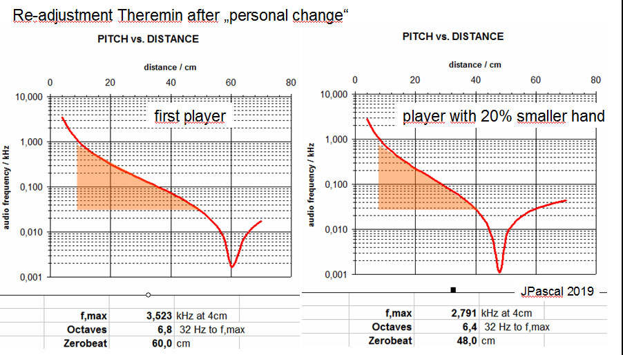
Please find here a simulation. I play the theremin and nulling is at 60 cm. A new person with 20% smaller hand comes. The adjustment is wrong. Now Re- adjustment the nulling to 60cm x 0.8 = 48 cm by using the offset function. The result for playability is now about the same.
You must be logged in to post a reply. Please log in or register for a new account.