Theremin Volume Control - What's Ideal?

Posted: 8/18/2016 5:19:04 PM
oldtemecula

From: 60 Miles North of San Diego, CA

Joined: 10/1/2014

Hi all,

The main area I have not developed in my research is a quality yet practical volume control printed circuit board. Once that is done I would not need the $96 EWS circuit board. The wood box and antennas are nice though!

Things I do not like about the EWS are the sound and second the use of a split power supply. This makes busking a little more challenging. If it was designed around a single supply of 9 volts dc it becomes more practical in all countries and not just an engineers wet dream.

You could easily use solar power, look mom no batteries.  (-;

Through serendipity long ago I found thermal drift could be nicely controlled by simply using TO-92 transistors that had a higher junction breakdown voltage. The ones I use in all my oscillators are rated at 300 volts. I tried some rated at 1000 volts and they were too stiff like the people who are trapped in the limits of computer modeling. The theory of why this works I leave for another conversation.

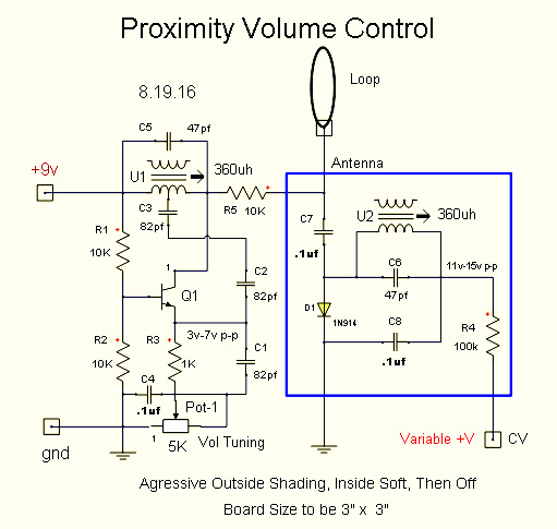
My not being the sharpest marble on this TW board allows me to ask a question. Is there any reason the schematic below could not be reduced to a single supply using a single transistor instead of using three?

The purpose of Q7 I have never been clear about, a mirror effect, what benefit does it add? Thermal drift?  Being in a two week wait period for my latest pcb maybe I will try to draw something up.

Does the capacitance of D1, C12 with L7 form a parallel tank circuit to match the Q6, Q7, Q8 frequency? 

Christopher


Posted: 8/18/2016 6:27:43 PM
dewster

From: Northern NJ, USA

Joined: 2/17/2012

"Is there any reason the schematic below could not be reduced to a single supply using a single transistor instead of using three?"  - Christopher

It could certainly be reduced to a single supply.  You would have to bias the bases of the transistors somewhere between ground and VCC.  Single transistor maybe if you went with a different oscillator topology.  I think Moog used +/- supplies here mainly because he already had to for the ICs, and it slightly simplifies biasing.

"The purpose of Q7 I have never been clear about, a mirror effect, what benefit does it add? Thermal drift?"

Q6 & Q7 form a differential pair, or long-tailed pair.  If you think of both bases being at the same potential, then both transistors will be conducting equally.  Raising the base of Q7 causes it to conduct more, which causes Q6 to conduct less, which allows the lower point of L14 to rise, which feeds the base of Q7 through C14, which causes it to conduct more, etc.  It's positive feedback that causes the oscillation to happen given the presence of the LC tank components.

Differential pairs are used as the input stage to most audio power amplifiers, and most op-amps.  They can have very high gain when the emitters are tied directly together like they are here, and if the collector impedances are kept high and loading is minimized.  You can gain a lot of insight into this type of oscillator via simulation, but you seem opposed to that.

"Does the capacitance of D1, C12 with L7 form a parallel tank circuit to match the Q6, Q7, Q8 frequency?"

I haven't analyzed it, so buyer beware, but I imagine what you are describing is the case.  There are two resonances, the oscillator LC and the antenna LC.  The oscillator stimulates the antenna tank and causes it to swing, and this is rectified or detected by D1.  Bringing the hand near the antenna causes the antenna LC resonance point to move away from that of the oscillator, and so the voltage swings get smaller in amplitude.  Kind of like pushing someone on a swing blindly at a fixed rate, and then doing something to the swing to alter it's natural rate.

It seems like this is an AM (amplitude modulation) situation, so prone to picking up interference, so something I'd probably never use, so it doesn't interest me terribly.

Posted: 8/18/2016 7:34:18 PM
ILYA

From: Theremin Motherland

Joined: 11/13/2005

"Does the capacitance of D1, C12 with L7 form a parallel tank circuit to match the Q6, Q7, Q8 frequency?

absolutely doesnt. The Q6/Q7/Q8 frequency (defined by the parallel tank circuit of L11+L14 and C14C15/(C14+C15)) should matching only the antenna resonance circuit (consisting of L7+L8+L9+L10 and antenna static capacitance ~10pF).

Properly speaking the oscillator frequency will be affected not only on the tank circuit but on the antenna resonance freq (hand position) too.

Posted: 8/18/2016 7:49:07 PM
ILYA

From: Theremin Motherland

Joined: 11/13/2005

Christopher,
I'm torn between my basic design (unfinished from 2011) and other small projects like TBM2. An other small project, unipolar EWS-like  theremin was simulated in LTspice and needs to be tested in hardware 1000 times (hi Thierry!).

Posted: 8/18/2016 8:42:05 PM
dewster

From: Northern NJ, USA

Joined: 2/17/2012

"absolutely doesnt. The Q6/Q7/Q8 frequency (defined by the parallel tank circuit of L11+L14 and C14C15/(C14+C15)) should matching only the antenna resonance circuit (consisting of L7+L8+L9+L10 and antenna static capacitance ~10pF)."  - ILYA

Oops, you're right, I wasn't thinking parallel or series, just LC in general.  But it definitely is series at the antenna with hand & intrinsic C.

"Properly speaking the oscillator frequency will be affected not only on the tank circuit but on the antenna resonance freq (hand position) too."

But that's a side effect, no?  Ideally the oscillator frequency wouldn't be influenced by the antenna LC, correct?

Posted: 8/18/2016 8:52:33 PM
oldtemecula

From: 60 Miles North of San Diego, CA

Joined: 10/1/2014

My opinion L7 & C12 are in parallel attached to series resonance out to the environment. Tomorrow will show my simpler version.

I believe capacitance loading on the antenna will change the current flow of the oscillator which will have some effect in the change of the osc frequency. It is the detuning of the antenna linear tank that has the most measurable effect.

Like ILYA I have many projects, they are all fun!

Christopher

Posted: 8/20/2016 2:14:00 PM
oldtemecula

From: 60 Miles North of San Diego, CA

Joined: 10/1/2014

Hi All,

I draw my schematic and think computer modeling could fine-tune the components in the blue square if this would work. Is anyone up for challenge?

As I try and conceptualize the EWS volume control a glaring fault begins to emerge. The way it would respond seems backward, I think a Thereminist would want aggressive response in the outside field and gentle wider response near the loop just before the sound is off?

If I were correct it would lead me away from passive volume sensing and back to my original PWM approach driving a Vactrol which removes any amplitude variations. I have many VTL5C1 to give away. Electronic parts are like candy, I can not get enough.

Looking at old notes a NSL32SR3 could replace the Vactrol?

My Harmonic Exciter board just needs two RF oscillators to get the opera sound so a generic PWM board could be used for Pitch and/or Volume and it will eliminate the need for the $96 EWS board. This is mostly a redesign of my original Phoenix PCB.

All of the above is thinking out loud.

The 5k tuning Pot will move the freq at 700khz about 25khz. This range can be reduced.

Christopher

Now this is really scary all my needed boards fit perfectly inside the EWS box. You can use any 12 volt power supply, AC or DC or even noisy switching. I use a 1 amp 7809 mounted on the bottom side of the pcb through a hole for outside ventilation.

The top pcb in the photo below has dual oscillators which sound better than an EWS using my 300v NPN's, then the buffer/breakout, then the Harmonic Exciter for that Clara sound and finally my own design of volume control using pulse width modulation for better volume shading. Yes I have been at this for 15 years. All of these boards are available for the adventurous if you can demonstrate soldering on previous projects, we must save the EM builders from themselves. This is what I meant over the years about building a theremin in a modular form so circuit sections can be added or removed.

Posted: 8/21/2016 2:27:19 AM
dewster

From: Northern NJ, USA

Joined: 2/17/2012

"As I try and conceptualize the EWS volume control a glaring fault begins to emerge. The way it would respond seems backward, I think a Thereminist would want aggressive response in the outside field and gentle wider response near the loop just before the sound is off?"  - Christopher

It all depends on the profile of capacitance change to the hand (~1/d), whatever voltage this produces as it moves the bandpass filter resonance point, and whatever the volume control circuitry does with this voltage.  Then there's the logarithmic response of the ear to loudness.  You might want to model it mathematically in Excel or something. 

As to what musicians are expecting, I'd guess linear loudness (in a dB sense) to linear hand distance.  Good luck with linear anything going the analog route.

"I draw my schematic and think computer modeling could fine-tune the components in the blue square if this would work. Is anyone up for challenge?"

I could help you do this yourself if you want to learn the rudiments of LTSpice.  Teach a man to fish...

Posted: 8/21/2016 4:36:57 AM
oldtemecula

From: 60 Miles North of San Diego, CA

Joined: 10/1/2014

Dew I think we would have a good time going fishing. My mentioning Modeling was trying to lure in one of the University students passing by. The comment on volume field behavior was to lure in a Thereminist.

Conversations at TW are drying up. I use to blame it on facebook but now I think the shallow input develops because everyone is using a smart phone. At the end of the day they are burned out from texting. 0-,

You and I view life through different prisms, that should be obvious to most. If the nurse pulls out a rubber glove and shoots some juice on a paper towel you know something digital is about to happen. I myself would view it as anal-log. surprised

Christopher


Posted: 8/21/2016 4:58:57 PM
oldtemecula

From: 60 Miles North of San Diego, CA

Joined: 10/1/2014

Валерия, я учусь поставки в Россию из государств-сложно и дорого. Все ТЕКСТОЛИТА, если я нарушу нижней платы только может поместиться в конверт 10 см x 15 см. Это самый практичный способ.

У меня 4-х слойная доска гармонический возбудитель до конца этой недели и смогут потом отправить досок.

Translation:

Valery, I'm learning supplies to Russia from the States is difficult and expensive. All of the PCB if I break the lower Board can be placed in the envelope 10 cm x 15 cm Is the most practical way.

I have a 4-layer Board harmonic exciter before the end of this week and then be able to send the boards.

Christopher

You must be logged in to post a reply. Please log in or register for a new account.