Linearity Meter

Posted: 11/16/2016 8:36:03 PM
dewster

From: Northern NJ, USA

Joined: 2/17/2012

"At the moment just my eyes can speak -). And they are talking about increased dispersion."  - ILYA

Oh, I think I see now.  It's the comparison of a 24 MHz crystal used as the time base vs. a PLL derived 23.986176 MHz.  That PLL must be kind of noisy (analog noise can be an issue with analog PLLs, they are often decoupled separately at the chip level).

If there is a bandwidth control on that PLL you might try reducing it.

Posted: 11/19/2016 4:38:34 PM
ILYA

From: Theremin Motherland

Joined: 11/13/2005

The first serious issue. Troubleshooting.

It is normal when you sure that everything is ok, but something lurks. An inspection of RF oscillator board found that the drifts of the "reference" and "main" cycles are not correlated over a longtime interval. The left graph shows the data taken from the 2000 s warm-up interval:


At zero point the RF board was turned on and logging was started. I am reminding that the same oscillator produces two frequencies corresponding connected and disconnected antenna states. This is done to neutralize the drift at serial measurements. Here, antenna is not installed, and the curves would have to be identical. But the graph shows that the curves are diverging. Suspicion fell on the relay.

At first,
another connection of relay has been checked. The changeover contact has been connected to tank, not to antenna terminal. The normally open contact was remained free.

Data for this variant are shown in the middle. Yes, the divergence becomes smaller. The warm-up drift is the same (350 Hz).

The relay autopsy has exposed the main disadvantage of this type of relay ("РЭС-15" in Russian, or "P3C-15" in English notation): the changeover contact is connected to the coil core. Here is a photo:


There is a significant parasitic capacitance between core and winding, but the worst thing is it has a huge  temperature coefficient. For case presented on the middle picture, this capacitance acts equally for both relay states, fortunately, so the curves are the same, more or less.

It seems to be good, but antenna must be grounded during the reference cycles (to prevent affecting via the pin to pin parasitic capacitance). Therefore it's necessary to look for a more suitable relay ...

For fun, I opened another relay, "РЭС-9" (or "P3C-9" in English notation):


Here, the changeover contact is separated from other elements by the dielectric pusher. This design had promised to work better, but unfortunately, the relay does not suit me on voltage, neither by size.

I found another relay, "РЭС-60" ("P3C-60" in English notation). Hermetically sealed case, the pins through the glass beads. I did not open it, just replace the old.  Unused pins (this relay has two pin groups) and metal body had been grounded.

Data for this variant are shown on the right graph. Not bad, isn't it? As a bonus, the oscillator warm-up drift was reduced to 150 Hz (more than 2 times).

Conclusions:
1. The cheap general purpose relays are not suitable. The specialized RF relays are required.
2. The warm-up time of the RF osc board is about 10-15 minutes.

The RF osc board, last version:


New relay, new air core coil. The extra collet contacts are soldered to antenna terminal and to relay's grounding wire to provide the calibrating/checking with reference capacitors. The collet contacts was extracted from the dip socket.

Posted: 11/19/2016 10:42:11 PM
dewster

From: Northern NJ, USA

Joined: 2/17/2012

ILYA, you might want to put 1" spacers under the oscillator.  I've found that wood interacts capacitively enough that I couldn't use it as the distance ruler attached to the antenna when I was doing my hand distance C measurements.

Posted: 11/21/2016 5:59:06 PM
ILYA

From: Theremin Motherland

Joined: 11/13/2005

"you might want to put 1" spacers under the oscillator"

Could be this better?

 I just dont want to lose some cm on "arm" level...

The warming-up drift with 0 pF capacitor (i.e. wo antenna) and after two-point (0 pF/99.8 pF)  calibrating:

With 0.2 s sample period:


A future "arm" (is cut from the decorative EPS tile):

and with aluminium foil:

Weight 14 g.


Posted: 11/22/2016 4:55:08 PM
ILYA

From: Theremin Motherland

Joined: 11/13/2005

Measuring of a 50 pF reference capacitor, 11 times (sample time is 2 s, parameters C1 and C2 are obtained during calibrating):

The first results with arm installed (just to check operating): 

Two of antennas have been measured. Sample time 0.2 s, 0.1 cm step, two way movement. An antenna D=11 mm has been measured  twice: firstly with a step 0.1 cm, secondly - with a step 0.1 cm at range 0...5 cm and with a step 1 cm at range 5...50 cm.


Schematic at the moment.

Some conclusions.

1. It is still puzzled to me, but the sample time 0.2 s is a best option, regarding to data divergence minimization.
2. Warming-up interval is 10...15 min.
3. The two way movement is superfluous.
4. A 1 cm step at 0.4 s step interval is quite acceptable on long distances (>10 cm) without accuracy degradation (despite significant relaxed oscillations of the "arm"). This allows to reduce a session time. By the other side, the microstep mode (0.1 cm step) lets me to monitor the data divergence and do more delicate data processing.
5. IMHO get raw data from the Meter and do all the data post processing (including calibrating) on PC was the true solution.

So, I am ready for points 1, 2 and 3. For experiments with different antennas, I'd like to start a new topic.

The Meter finished:

Posted: 11/22/2016 6:33:23 PM
dewster

From: Northern NJ, USA

Joined: 2/17/2012

"Could be this better?"  - ILYA

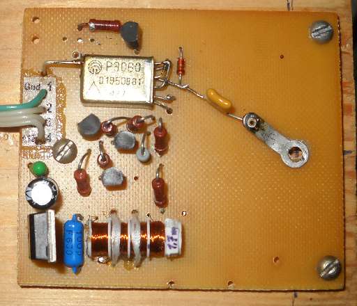
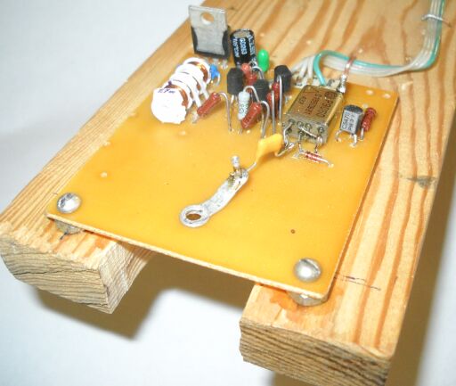
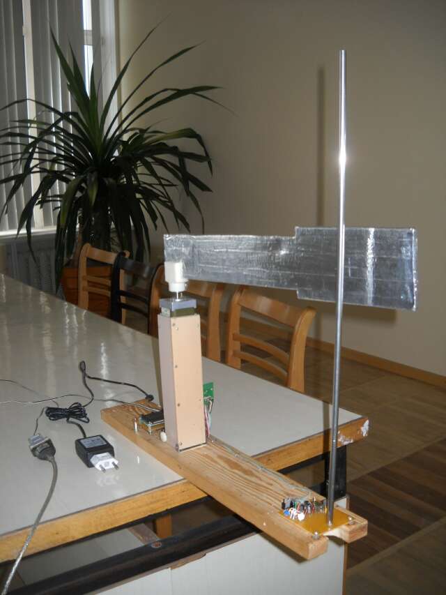
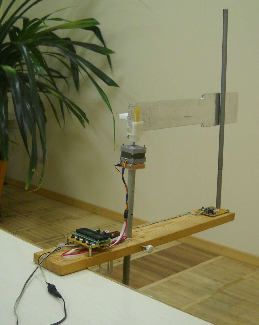
I know it gets used a lot in Theremin cabinetry and such, but for scientific experimentation I just don't trust wood to be neutral when it comes to C.  I'd space the PWB sufficiently above the wood, or better yet make the base underneath plastic.  But ultimately I think the oscillator topology is just barely stable enough for what you are doing.

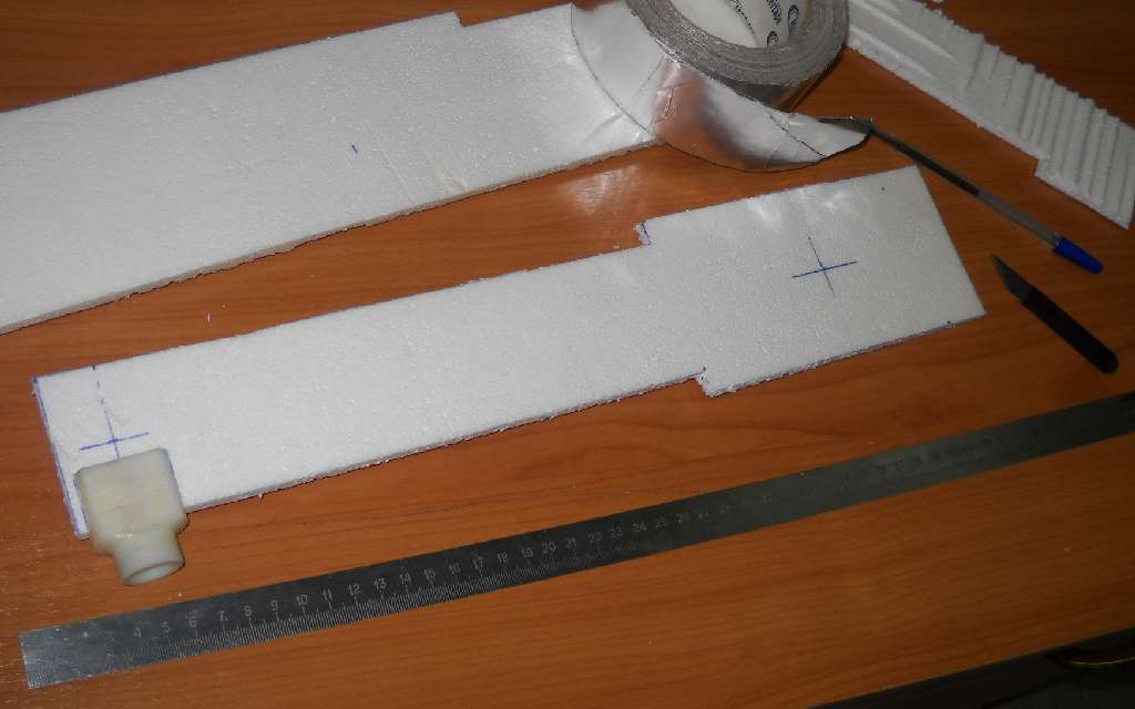
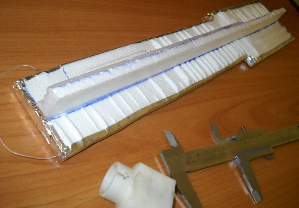
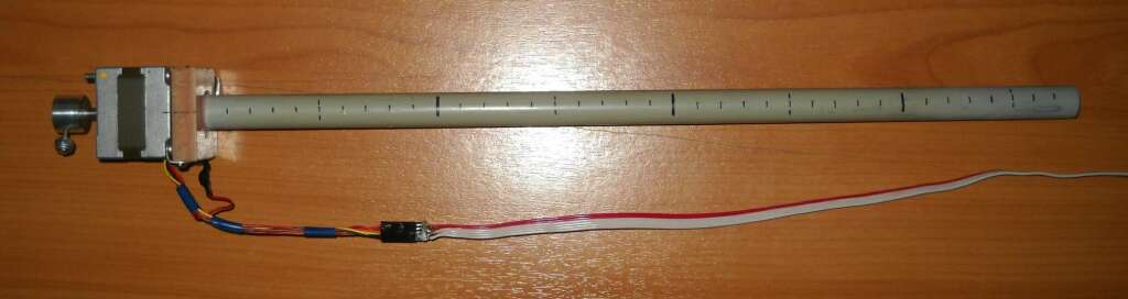
If you need to cut weight, the aluminum coating on the arm can be a single side, I don't think coating all sides, or making it 3D is necessary.

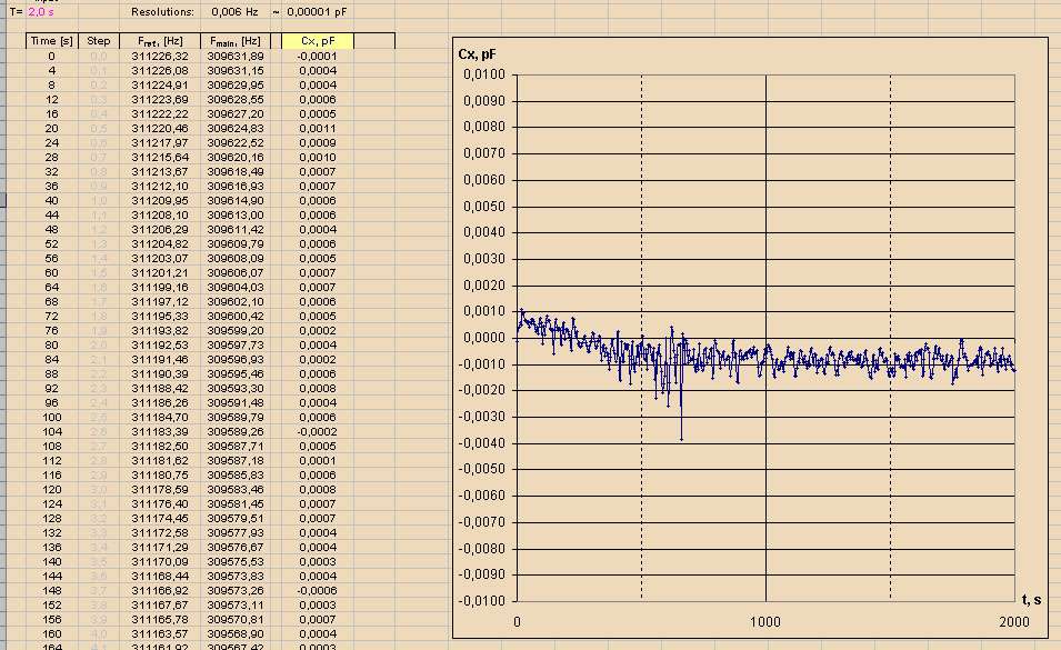
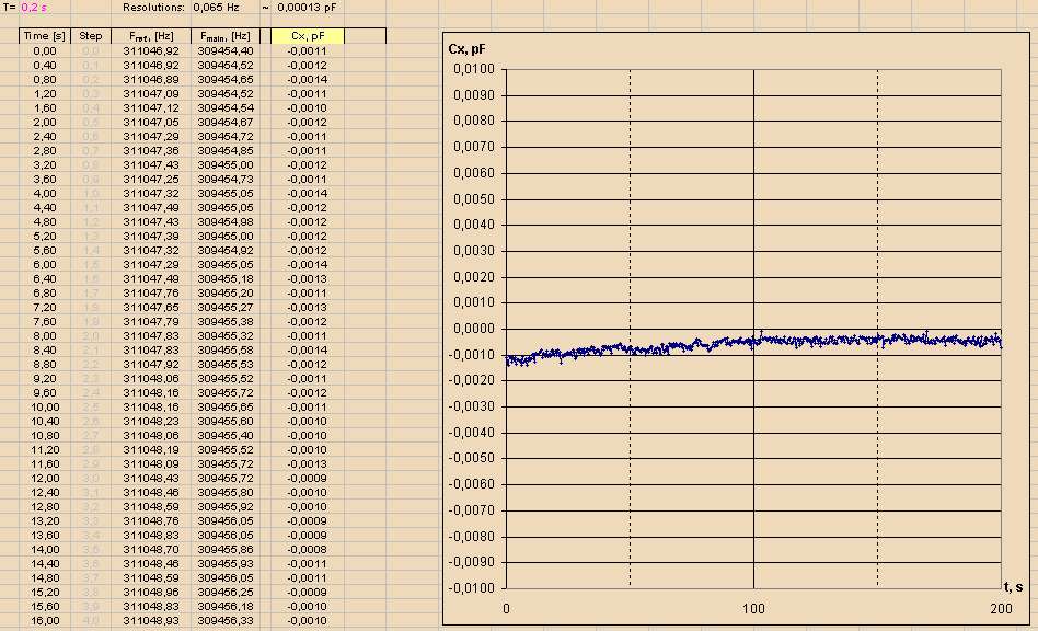
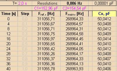
"1. It is still puzzled to me, but the sample time 0.2 s is a best option, regarding to data divergence minimization."

I don't get this either, a longer sampling interval should give you smaller noise because of the implicit integration.  All I can think is math noise, or some magnification of the mains noise due to the sampling interval (I see tons less noise on the scope when the trigger delay is a multiple of the mains period).

"2. Warming-up interval is 10...15 min."

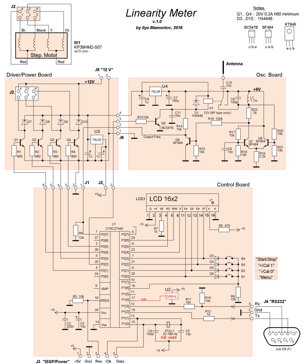
This seems really excessive to me.  Long warm-up may confound your results down the road.  You want an ultra stable oscillator topology that doesn't need more than maybe a minute max in order to stabilize.  In particular, oscillators that don't have a nice clean sine wave happening at the tank should be avoided.

Ilya, I hope I'm not driving you too crazy with my nit-picking, this is a very interesting project and I very much appreciate your sharing it with us!

Posted: 11/23/2016 4:19:50 PM
dewster

From: Northern NJ, USA

Joined: 2/17/2012

Ilya, a suggestion:

When you do your plots of C vs. distance (d), you might try using 1/d instead for the x axis.  You're plots will be somewhat less intuitive to read, but they should look a lot more linear that way.

Posted: 12/6/2016 5:12:56 PM
ILYA

From: Theremin Motherland

Joined: 11/13/2005

"how do you get the "hand" positioned in the center of the various length antennas?" - dewster

"However for consistency in your testing, you should probably approach the vertical center of every "test antenna" - randy george

The new motor holder:

which provides the variable height:

 EDIT: The discussion on measuring antenna capacitance is here.

You must be logged in to post a reply. Please log in or register for a new account.