Measuring Antenna Capacitance

Posted: 12/16/2020 6:27:06 PM
ILYA

From: Theremin Motherland

Joined: 11/13/2005

"Natural hand" vs. different "hands" of 2016.

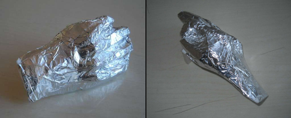
I'm not Michelangelo or even Tsereteli, but i did try to make a plausible model of hand (using styrofoam).
The fingers are approximately in 2nd aerial position and the outward surface is covered by self-adhesive aluminum foil (which has electrical contact with the rest of the "hand").


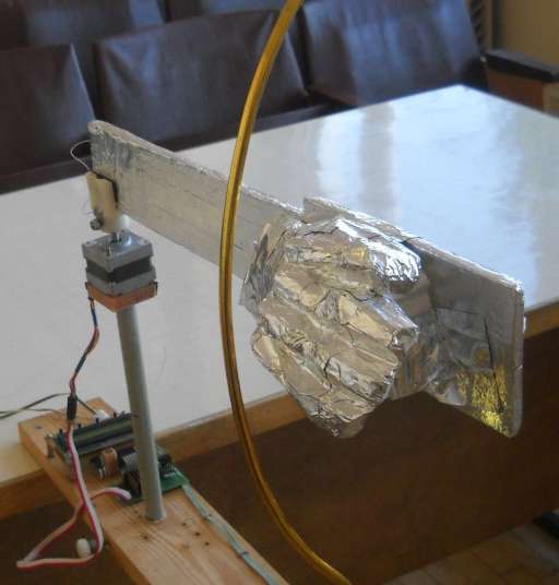
Unfortunately, the whole structure became heavier, which led to increased hand mechanical oscillations at step movement.
For some reason this was not reflected on measurement results  (refer blue graph). Other graphs are correspond to hand shapes of 2016.

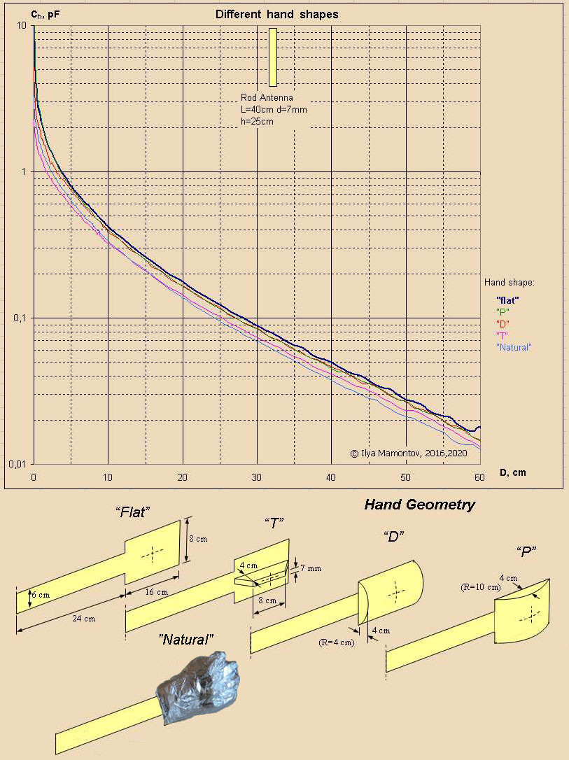
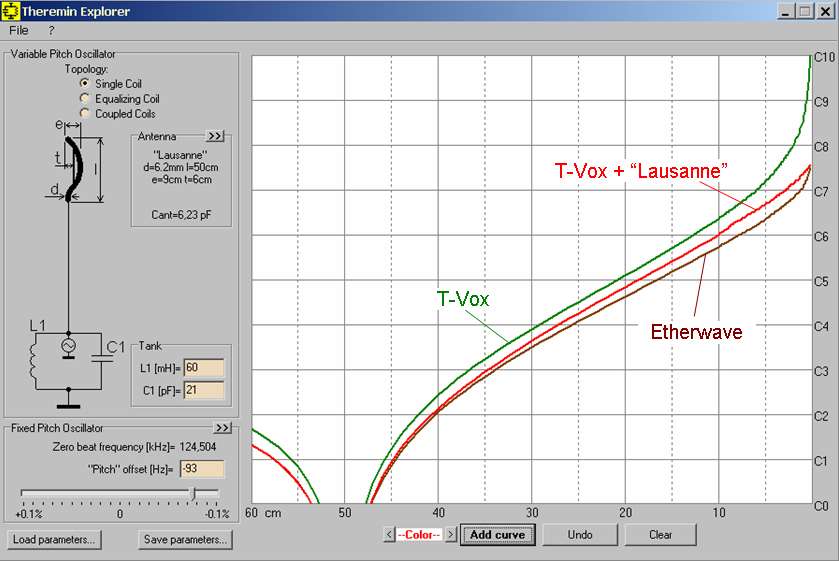
As you can see, the best match is given by model "T".
Possible by varying the height/thickness/angle of the perpendicular wall, you can achieve a better matching.

Posted: 12/17/2020 11:32:27 AM
dewster

From: Northern NJ, USA

Joined: 2/17/2012

Fantastic work ILYA!

Have you considered the resistive element of the human body?  I feel kinda bad that I haven't tried to quantify this in any way. 

Resistive damping seems to be the reason why oscillation amplitude tends to drop as the hand approaches the antenna, and why oscillation often stops with direct hand contact, even when there is a small series capacitor between the oscillator and antenna.  Damping might not affect the oscillation period much, but it would be nice to have even a rough model of what is going on, if only for simulation purposes (spicing oscillators could have a stronger predictive value of actual operation).

Maybe articulate a cadaver with stepper motors?  (I kinda keed - good luck putting that in storage!)

Maybe even just a single resistor from your tinfoil hand to ground would do it?

Posted: 12/18/2020 4:43:29 PM
ILYA

From: Theremin Motherland

Joined: 11/13/2005

cadaver = too dead gentleman?
Ughhhh...

I thought about a resistor between "hand" and ground, but not as a contributor to diminishing of Q,
but as a factor of  hand-to-frequency effect degree.

That is one of the points TODO. Unfortunately one of the reasons to get new data forced is the need to use the setup for other experimentations (as a precise freq meter).

Posted: 12/18/2020 4:48:37 PM
ILYA

From: Theremin Motherland

Joined: 11/13/2005

Curved antennae.

As became clear from experimentation of 2016, the long antennae have a benefit in linearity domain. The diameter does not affecting at all.Analyzing this phenomenon, I assumed that better results will be obtained with antennae which ends are curved toward the performer hand.

For checking, such the antennae was used:

In first case, antenna was composed of straight segments, the second  antenna was shaped as arc.
The graphs below do comparisons with linear antennas which have same dimensions (diameter and overall size).

The estimation of antenna linearity is somewhat problematic. I don't have any ideas about the exact mathematical criterion yet, so we still have to use a visual assessment of the shape of graphs (which is quite subjective).

I use the fact that the graphs which are linear in logarithmic C axis will produce a linear response in pitch domain.

clarification: I don't have any data for, say, 6.2 mm diameter rods. The corresponding curves were obtained using linear interpolation of nearest dimensions (on data of 2016). Inclined lines are drawn for clarity - to assess the degree of deviation of real curves from some idealized case.

Both antennas (segmented and arc) show a reduced capacitance increase in near antenna field (compared to straight ones), but I would not say that the effect is much pronounced.

Posted: 12/18/2020 5:28:10 PM
dewster

From: Northern NJ, USA

Joined: 2/17/2012

"... I assumed that better results will be obtained with antennae which ends are curved toward the performer hand."  - ILYA

I might (naively) assume the opposite?  A rod curved away from the performer in far-field would more or less behave like a regular straight rod, but in the near-field would interact with the hand less?  A possible test of this would be to have a sideways 'V' shaped antenna, with no straight vertical segment.  Or maybe even a sideways 'W' antenna to minimize the near-field.  Where is Peter Pringle's lightning bolt antenna when you need it? ;-)

Though I suppose by curving it towards the performer you are slightly increasing far-field interaction, and the overall linearity is a result of the hand (and body) at all points. 

I must say, mere "closest proximity" is a much stronger determinant of C than I imagined before embarking on this kind of testing.  It fairly overwhelms everything else.

Posted: 12/18/2020 7:49:12 PM
pitts8rh

From: Minnesota USA

Joined: 11/27/2015

I've run across some online visualizers for E and H fields that can be fun to play with if you don't have the good stuff like Ansoft HFSS (which I don't anymore ).  Here is one applet that I had bookmarked a while back:

https://www.falstad.com/vector3de/

You can select some canned conductor shapes and display the field lines around them in 3D or look at cross-sectional slices. If you select a finite line and choose to display equipotential lines (which are really wireframes of equipotential surfaces in 3D) you will see the characteristic constant-pitch field shape around the rod antenna.  This changes from oblate spheroid in the mid-field to nearly cylindrical at near range and spherical at far.  I think there are other apps out there that might let you draw your own simple conductor shapes.

I have no doubt that non-traditional antenna shapes could be used to improve specific flaws in pitch fields that are sort of grandfathered in.  But players that have learned to work with existing quirks may not like the feel of something that has been "corrected".  I mean we can't even agree on whether linearity is a good thing, nor should we try to.  There are so many different ways that different players' arm movements and finger articulations intercept the target pitch "surface" around the antenna that this is sort of a can of worms to mess with. I dislike plate antennas for this very reason (sorry Eric!).

I'm on the fence about messing with tradition when it comes to musical instruments. I keep thinking that you wouldn't dare try to come up with a new and improved piano keyboard design with different key shapes or spacings, etc. thinking that musicians would immediately flock to it and be willing to change their playing technique to embrace your new idea.  But then someone like Roger Linn comes along and designs the LinnStrument that throws all convention out the window and starts fresh with great ideas.

Posted: 12/19/2020 2:40:56 PM
ILYA

From: Theremin Motherland

Joined: 11/13/2005

Being in Lausanne (Switzerland) in 2005, I could not have imagined that this waterfront sculpture would become a prototype of theremin antenna.

(BTW, someone of TW members lives in Lausanne, how this sculpture is titled?)

Posted: 12/19/2020 2:44:00 PM
ILYA

From: Theremin Motherland

Joined: 11/13/2005

"Lausanne" antenna.

Such antenna has a dielectric barrier that prevents approaching the hand to conductive surface. This barrier creates a kind of visual center to which the hand is stopped, besides, this center becomes a new reference (zero) point for distance axis.

The capacitance curve for "Lausanne" type is presented below.
Can this type of antennae compete with an equalizing coil?

Noteworthy the previous antennas have a psychological effect, which disorientates the player and shifts the expected extreme point of movement from antenna surface to illusory center of "air segment".

Posted: 12/26/2020 11:33:40 AM
ILYA

From: Theremin Motherland

Joined: 11/13/2005


Posted: 12/26/2020 11:38:29 AM
ILYA

From: Theremin Motherland

Joined: 11/13/2005

I put the data of "Lausanne" antenna in Theremin Explorer application (updated version is expected soon) to see how characteristics of different theremins will be changed.

A hypothetical pitch response of T-Vox  with "Lausanne" antenna is shown below (red curve). A pitch field of original T-Vox is green. For comparison, I also put here the EW response (brown curve). The EW has 30 mH equalizing inductance and a tuning according the "Hot-Rodding..." manual. A zero beat point was set at 50 cm distance for all cases.

The result is as follows: "Lausanne" type turns T-Vox into "more linear version" of Etherwave.
Which price? Narrower pitch range.

I don't know how much the wide pitch range of original T-Vox is useful for player. Like other theremins w/o EQ coil the T-Vox has a quite compressed high register. My Paradox and Paradox-MX theremins (you know the EW Pro is too) have a special switch to expand the playable pitch range.

BTW, I tried out the curved antenna on Paradox and got a lot of funs with playing new version. However I got the same fun when I returned to straight antenna. That is paradox!
(Sure this is due to the joy on returning to familiar sensing)

PS. Actually, "Lausanne" works in the same way as the equalizing coil in Etherwave: both of them create a kind of "barrier". In dual coil circuits it is done purely electrically, in "Lausanne" antenna - mechanically. A significant advantage of "mechanical" method is the lack of additional "magic" adjusting.

You must be logged in to post a reply. Please log in or register for a new account.