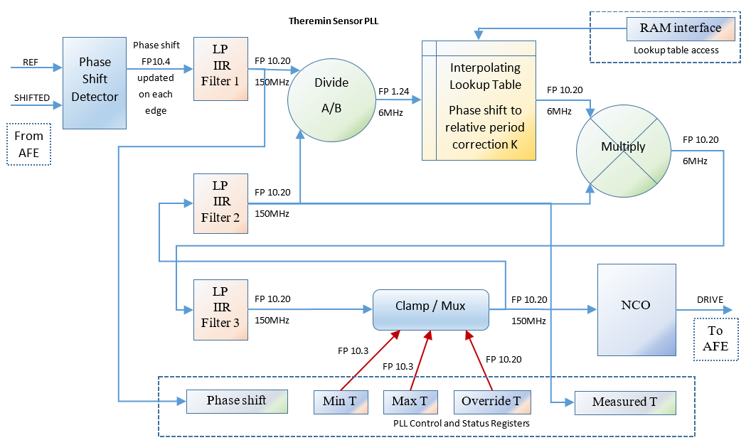
Ah, in that case the D-Lev LCDPLL is soft (LUT+FF) and not a special PLL hardware block in the FPGA.
-- dewster
I was sure that you are using some hardware block. So, PLL I'm developing will be close to your one.
I use the DDR element at I/O. With core clock of 180MHz this gives 360MHz effective resolution,
which is sufficient - but you always want everything you can get here, and if I had your 8x serdes I'd be using it for sure.
-- dewster
Then I can be sure that 1.2GHz resolution should be enough.
Tried to search altera docs for SERDES hardware blocks.
LVDS SERDES (ALTLVDS) docs say:
Turn off this option to use the dedicated SERDES circuitry in
the device. When you implement the dedicated SERDES in
the LVDS transmitter, the SERDES connects to the LVDS
transmitter; therefore, the output of the transmitter cannot
be assigned to single-ended I/O standards.
This feature is supported in Arria GX, Arria II GX, Arria II
GZ, HardCopy® II, HardCopy III, HardCopy IV, Stratix,
Stratix GX, Stratix II, Stratix II GX, Stratix III, and Stratix
IV devices. In Cyclone series, except Cyclone V devices, the
SERDES is always implemented in logic cells. Cyclone V
devices contain dedicated SERDES circuitry.
Are you using Cyclone?
In Xilinx devices, even Spartan 6 has SERDES blocks.
Yes, the gain increase at resonance is Q/pi, another reason you might as well treat the entire system as linear,
though when it isn't locked the search for lock is significantly slowed down due to the lowering of the loop gain.
-- dewster
I'm going to profile F_drive/F_resonance to phase_shift during calibration and set interpolation table
based module which should calculate LC resonance frequency based on F_drive and phase_shift.
For the LCDPLL to be a low pass filter for phase noise, the integrated phase error should be used as the NCO input.
The phase error is attenuated to set the loop bandwidth, and I use powers of 2 here because the bandwidth doesn't need to be any closer than that,
and right shifting to attenuate is free in digital logic.
-- dewster
I'm using the same approach for LP filters - right shift as filter K. What number of stages is reasonable?
I'm simulating filter response using Excel - as you suggested. For me, 2-stage response looks good.
I apply the 48kHz triangular dither directly to the NCO drive (frequency) control.
-- dewster
Looks like the best point for adding dithering for me.
Then I'm looking at the phase difference between the two ends of the coil for 90 degrees, which is easily detected via XOR.
I sample the phase inputs (via DDR) before XOR rather than after because the DDR elements are at the pins.
I've got the dither frequency set significantly above the LCDPLL loop bandwidth so it isn't tracked by the loop.
Too much dither (amplitude) can make the LC really bobble around, and I don't know how to quantify the upper limit of useful
dither (this is variable via a front panel knob, with 2x for each detent via shifting in digital logic).
-- dewster
I believe reasonable amount of dither should not go too far from resonance.
Did you see any difference in playing performance experience with high and low dither?
You can use an XOR if you generate an internal quadrature NCO signal,
I had code to do that at one point when I was still going down the heterodyning path IIRC.
XOR is superior in this application because it is immune to edge noise (the NCO will be clean but the coil sense won't be) though
XOR can lock to harmonics.
One possible down side to single point sensing is: any differential
delay for the phase comparison paths can become a drift issue if it has any thermal dependency.
-- dewster
In my approach, generating of PI/2 phase inside NCO will cause phase drift.
In this case, serdes delay + FPGA output + comparator delay will be included into phase shift, and can vary, e.g. with current sensing comparator delay changes due to temperature drift.
To minimize phase drift, I'm using two identical comparators: one just sends drive signal back as is, and second - measures current.
I hope that drift in both paths will be the same, and will not affect phase difference seen by FPGA.
Since, I found method for phase shift measure near zero in FPGA, XOR will not give any benefits.


