Aside from being a total nightmare of wires flying everywhere still (waiting on some RF chokes to try in place of the massive wirewound resistors for power supply decoupling before I start soldering the guts) the pitch section has come mostly to life - I have not yet wound a coil for / connected a proper pitch antenna, but by varying the oscillator tuning I'm able to manually sweep the frequency, and the oscillators respond to my hand's proximity in a decidedly theremin-like fashion.
The two issues I've got at the moment are both related to the EF86 I'm using as a mixer tube.
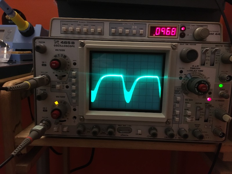
The first issue is that the tube is is biased into cutoff by the negative voltage swings (flat upper peaks on the scope as the output hits the power supply voltage). This may not actually be a problem: Per at least one source (https://www.thereminvox.com/article/articleview/28/1/2/index.html apparently taken from Moog's notes) the Rockmore theremin behaved similarly, though as we have no waveform data from that unit as far as I know it's hard to determine if this is entirely correct. Henk's construction photos include waveforms and mine are broadly similar (I expect the differences are probably due to the lack of a coupling capacitor, and also my tapping off the grids of my oscillator tubes to feed my mixer which is convenient but probably not optimal).
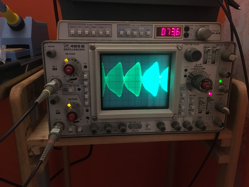
The second issue is that my waveform is "fuzzy" at its peaks: RF is bleeding through from the previous stages. I suspect this one is related to the fixed resistance I currently have in series with the control grid (G1) of the EF86 (15K Ohm - closest loose resistor to the RCA Standard 10K I had laying around without busting open a bag) and the lack of any resistance in series with the screen grid (G2) - prior to adding the resistor to G1 the entire waveform was a fuzzy mess of aliasing because the signals weren't balanced (G1's RF component was swamping the audio-frequency output). Some experimentation and two potentiometers as in the Rockmore theremin design should allow me to clean this up by matching the input waveform magnitudes.
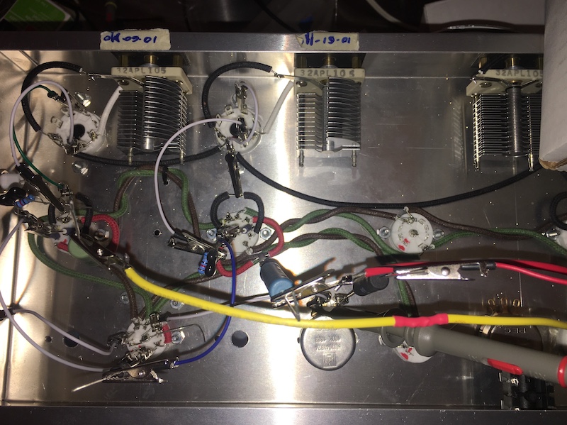
Obligatory disaster porn - The current state of the alligator clips and jumper wire internals:

and the current output of the mixer tube (96.8Hz):

Not pictured: The new shield plates on the top side of the chassis (because if I flip the stupid thing over right now parts will start falling out), but if you follow the mounting screws from the variable pitch oscillator's tuning capacitor (top left) toward the mixer tube (bottom left) you'll see two screws almost in line wtih that socket's mounting screws. That's the back of the shields, and the front is attached to the capacitor mounting screws.
Two shields are employed to balance the capacitive effect on the oscillator coils & keep the zero-beat point for the pitch oscillators close to center on both trim capacitors.
Obligatory Safety Warning:
In these photos you've seen me put 300 volts at half an amp through precariously balanced resistors and alligator clips sticking out of an open chassis like the quills of an electrified porcupine waiting to arc and short at the slightest breeze. As a result there is a not-insignificant risk I will fry components, start a fire, or even kill myself. I am a dangerous idiot, and you should employ better electrical safety practices when prototyping equipment.
Don't be like me - it's a miracle I've lived as long as I have.


