Teensy 4.0 600MHz ARM Cortex M-7 MCU - ideal for digital MCU based theremin?

Posted: 10/7/2019 7:49:44 AM
Buggins

From: Porto, Portugal

Joined: 3/16/2017

I've noticed that new small but powerful Teensy series MCU board Teensy 4.0 became available recently at cost of $19.95.

Looks like ideal for Open.Theremin core replacement.

Benchmarks:

Technical Specifications
* ARM Cortex-M7 at 600 MHz
* 1024K RAM (512K is tightly coupled)
* 2048K Flash (64K reserved for recovery & EEPROM emulation)
* 2 USB ports, both 480 MBit/sec
* 3 CAN Bus (1 with CAN FD)
* 2 I2S Digital Audio
* 1 S/PDIF Digital Audio
* 1 SDIO (4 bit) native SD
* 3 SPI, all with 16 word FIFO
* 3 I2C, all with 4 byte FIFO
* 7 Serial, all with 4 byte FIFO
* 32 general purpose DMA channels
* 31 PWM pins
* 40 digital pins, all interrrupt capable
* 14 analog pins, 2 ADCs on chip
* Cryptographic Acceleration
* Random Number Generator
* RTC for date/time
* Programmable FlexIO
* Pixel Processing Pipeline
* Peripheral cross triggering
* Power On/Off management


ARM Cortex-M7 brings many powerful CPU features to a true real-time microcontroller platform.

Cortex-M7 is a dual-issue superscaler processor, meaning M7 can execute 2 instructions per clock cycle, at 600 MHz! Of course, executing 2 simultaneously depends upon the compiler ordering instructions and registers. Initial benchmarks have shown C++ code compiled by Arduino tends to achieve 2 instructions about 40% to 50% of the time while performing numerically intensive work using integers and pointers.

Cortex-M7 is the first ARM microcontroller to use branch prediction. On M4, loops and other code which much branch take 3 clock cycles. With M7, after a loop has executed a few times, the branch prediction removes that overhead, allowing the branch instruction to run in only a single clock cycle.

Tightly Coupled Memory is a special feature which allows Cortex-M7 fast single cycle access to memory using a pair of 64 bit wide buses. The ITCM bus provides a 64 bit path to fetch instructions. The DTCM bus is actually a pair of 32 bit paths, allowing M7 to perform up to 2 separate memory accesses in the same cycle. These extremely high speed buses are separate from M7's main AXI bus, which accesses other memory and peripherals. 512K of memory can be accessed as tightly coupled memory. Teensyduino automatically allocates your Arduino sketch code into ITCM and all non-malloc memory use to the fast DTCM, unless you add extra keywords to override the optimized default.

Memory not accessed on the tightly coupled buses is optimized for DMA access by peripherals. Because the bulk of M7's memory access is done on the 2 tightly coupled buses, powerful DMA-based peripherals have excellent access to the non-TCM memory for highly efficient I/O.
Teensy 4.0's Cortex-M7 processor includes a floating point unit (FPU) which supports both 64 bit "double" and 32 bit "float". With M4's FPU on Teensy 3.5 & 36, and also Atmel SAMD51 chips, only 32 bit float is hardware accelerated. Any use of double, double functions like log(), sin(), cos() means slow software implemented math. Teensy 4.0 executes all of these with FPU hardware.

512K is mostly enough for reverb.


600MHz floating point processing is enough for audio DSP algorithms.

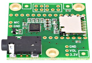
There is easy to use audio board which provides stereo 16bit 44100Hz audio I/O with headphones amplifier and Line In/Line Out. Cost: $13.75

Overclocking of MCU to 900-960MHz seems ok with heatsink.

I'm going to check for possible timer resolutions which can be used for theremin sensor frequency measure.

There are S/PDIF input and output pins.
I hope it would be possible to simple solder optical transmitter and receiver (like EVERLIGHT PLT133/PLR135) to have digital audio i/o.

For theremin sensor, we can use si5351 clock generator breakout for reference clocks + D-triggers (+ optional dividers) for heterodyning conversion of oscillator frequencies to easy measurable frequencies. Fast MCU should have good timer resolution for frequency measurement.

USB host connector can be added for connection of some extensions.

USB slave interface used for programming and power may provide USB slave devices as well - e.g. MIDI interface.

4 wire SPI/SDIO may be used for SD card interface.

So far, I've ordered Teensy 4, audio board for T4 (from PJRC), and 3.2" capacitive touch screen (ILI9341 spi interface, i2c for touch), and si5351 clock gen breakout - for experiments.

Posted: 10/7/2019 2:24:59 PM
Thierry

From: Colmar, France

Joined: 12/31/2007

Looks promising. But, IMNSHFO, your approach is not optimal. Normally, in a professional environment, you would develop your concept for a MCU based theremin in an abstract way, first, then find out the required specifications which the MCU in your project needs to have, and finally, after studying data sheets, decide which MCU would be best suited for your project.

You seem to have found a motor and you ask if and how to build a car around it. Normally, the car is designed first, and then a motor is selected to make it advance.

Posted: 10/7/2019 4:26:58 PM
oldtemecula

From: 60 Miles North of San Diego, CA

Joined: 10/1/2014


- No one was interested due to horrible latency at the starting line, then again it just sounded bad -


Posted: 10/7/2019 5:10:11 PM
Buggins

From: Porto, Portugal

Joined: 3/16/2017

Looks promising. But, IMNSHFO, your approach is not optimal. Normally, in a professional environment, you would develop your concept for a MCU based theremin in an abstract way, first, then find out the required specifications which the MCU in your project needs to have, and finally, after studying data sheets, decide which MCU would be best suited for your project.You seem to have found a motor and you ask if and how to build a car around it. Normally, the car is designed first, and then a motor is selected to make it advance.

This MCU board is what I was waiting for long time.
I'm sure this H/W is good enough for building digital theremin.
Power of 900MHz ~2 instructions per cycle is even more powerful than Dewster's FPGA build. It's guaranteed up to 20000 instructions per 44100Hz sample. 

Previous Teensy (3.6) is 5 times slower, and doesn't have enough SRAM for reverb.
Teensy 4 is at least 300 times faster than Arduino UNO used for Open.Theremin.
Theremin sensor hardware I'm going to use has much better sensitivity than one on Open.Theremin, so I hope it would be pretty playable.

Regarding latency, Teensy Audio library can be adjusted to have lower latency ~1-2ms or even less (by changing DMA frame size - increased CPU frequency allows to have bigger I2S DMA interrupt rate). It's non-audible delay.
Peter Termen, theremin player, uses notebook + audio card for adjusing analog theremin sound while playing - and doesn't feel that its latency is boring (I believe, sound card latency is >=3ms).


No one was interested due to horrible latency at the starting line, then again it just sounded bad

Didn't expect anything else from oldtemecula.

Posted: 10/7/2019 5:14:38 PM
dewster

From: Northern NJ, USA

Joined: 2/17/2012

Thank you Buggins for bringing this to our attention!  Amazing what they're able to cram on an inexpensive little board these days.  512KB / 48k / 4 (32 bits) = 2.66 seconds, probably enough for some form of reverb.  What timing resolution do you think it can achieve for the axes?

And I don't see this is a solution in search of a problem.  You clearly understand the processing features you need to do the job and are selecting accordingly, not the other way around.

Posted: 10/7/2019 5:24:18 PM
ILYA

From: Theremin Motherland

Joined: 11/13/2005

Buggins,
has this MCU a 600 MHz capture timer on the board?

Posted: 10/7/2019 5:30:51 PM
Buggins

From: Porto, Portugal

Joined: 3/16/2017

Default sample rate of Audio Shield is 44100 (although SGTL5000 IC supports 48K and 96K sample rates as well, and 24 bits per sample instead of 16 defined in audio library).
SRAM size is 1MB. If 256KB is enough for program+data, the rest (768K) might be used for reverb storage. When you say 32bits per sample, do you mean stereo 2x16bit, or 32bit precision of sample?

What timing resolution do you think it can achieve for the axes?

Axes?


Posted: 10/7/2019 5:32:55 PM
Buggins

From: Porto, Portugal

Joined: 3/16/2017

Buggins,has this MCU a 600 MHz capture timer on the board?

Need to check. Previous board (Teensy 3.6) with 180MHz clock had only 60MHz bus clock (timer clock) with possible overclocking to 90MHz.

UPD: Teensy 4.0 has dynamic CPU and BUS clocks.

As far as I understand from clockspeed.c code, F_CPU / F_BUS divider is being set to have value close to 150MHz, but not lower than F_CPU/4.

Code:
uint32_t div_ipg = (frequency + 149999999) / 150000000;
if (div_ipg > 4) div_ipg = 4;
...
F_CPU_ACTUAL = frequency;
F_BUS_ACTUAL = frequency / div_ipg;

So, for 600MHz, F_BUS (timer resolution) will be 150MHz, but for 900MHz (overclocked) - 225MHz.
Not sure if it's ok to change this code to make divider bigger (overclock BUS_CLK).

According to FreqMeasure library source code, timer resolution is F_BUS_ACTUAL.

If not enough, timer resolution may be increased 2 times, by changing active level from Raising edge to both edges.
Additionally, two different timers with different base clocks (Teensy 4.0 has 7 PLLs). Need to check NXP iMXRT1062 datasheet for details.


Posted: 10/7/2019 5:34:45 PM
dewster

From: Northern NJ, USA

Joined: 2/17/2012

"When you say 32bits per sample, do you mean stereo 2x16bit, or 32bit precision of sample?" - Buggins

I would do 32 bit precision.  Reverb is a filter, and you don't want the decay tails sounding "grainy" or otherwise weird.

"Axes?"

The pitch and volume antenna numeric responses, I tend to call them axes.

Posted: 10/7/2019 8:20:07 PM
Buggins

From: Porto, Portugal

Joined: 3/16/2017

"When you say 32bits per sample, do you mean stereo 2x16bit, or 32bit precision of sample?" - BugginsI would do 32 bit precision.  Reverb is a filter, and you don't want the decay tails sounding "grainy" or otherwise weird."Axes?"The pitch and volume antenna numeric responses, I tend to call them axes.

Let's caclulate expected sensitivity of sensors.

1) Oscillator output frequency range.

As sensor input, we will have digital output of oscillator.
Since we don't need to reduce oscillator Fmax/Fmin to audio signal range like in analog theremins, we can implement maximal sensitive oscillator,
w/o capacitor parallel to L. Antenna C changes from ~7pF to 9pF, and oscillator F decreases by ~7-8% while hand approaches antenna.

Let's take Fosc is 1MHz for far hand to antenna distance, and 1MHz-7%=0.935MHz for hand near antenna.

2) Direct measure of frequency.

Let timer resolution is 150MHz, so we can measure time intervals in count of 1/150MHz intervals.

Using direct measure of osc frequency, we will get values 150 for max frequency, and 161 for low frequency, 1000000 times per second.
Measure of signal frequency uses interrupt on selected edge (or both edges) of pin, which takes and stores latched value of timer counter.
Having interrupt rate of 1000000 per second is a waste of time. But we can add external (or internal - if hardware allows) divider.
For frame rate 1000Hz(1ms), averaging would give us values x1000 bigger: 150000..161000
161000-150000 = 11000 different values, a bit more than 13 bits if useful data.
It's not enough sensitivity for distances far from antenna.

3) Adding heterodyning

How to increase sensitivity? Let's use heterodyning based on D-trigger. Connect OSC input to C input of D trigger, and reference frequency Fref to D input.
D trigger output will be near difference between Fosc-Fref.
For better result, Fref should be indepenent from measurement timer clock (otherwise there will be aliasing).
Most likely, Teensy 4 can produce necessary clocks, since it has 7 PLLs.

Fref has to be chosen to convert frequencies difference to have big enough Fmax/Fmin, but keeping Fmin > framerate and Fmax Tmin => 150000000/12500=12000
Fmin'' => Tmax => 150000000/3750=40000
Tmax-Tmin = 40000-12000 = 28000 ~15bits

Sound will be generated by frames (e.g. 1ms frame for 48KHz is 48 samples). Pitch and frequency will be interpolated for each 48 samples of frame from previous value near first sample of frame to new measured value near last sample of frame).

We will need new sensor value for each frame (e.g. 1ms) - and we can average at least values since last frame (12..13 values for Tmin, or 3..4 values for Tmax)
It will give us 2-3 additional bits w/o increasing of input latency.
Playing with averaging filter (e.g. allowing bigger averaging for hand far from antenna) we can choose bitween bigger number of bits / bigger latency, and lower number of bits/lower latency.
1 additional bit may be obtained if we measure period of signal on both edges instead of single one.
Choosing Fref closer to Fosc could increase number of bits as well.
(What is better, to have Fref>Fosc or Fref

So, my estimation of sensor sensitivity is ~17-18 useful bits in measured value (if averaging length is ~ frame rate).

Increasing of Ftimer (Fbus) - overclocking would give a bit better sensitivity.
As well, if there are enough pins, each OSC output might be measured more than by one time - e.g. having additional Fref and D-trigger and measuring timer would gave one additional bit of precision. (Oversampling)

Not sure how many bits will be left for low notes after linearization if 18bits.


You must be logged in to post a reply. Please log in or register for a new account.