Teensy 4.0 600MHz ARM Cortex M-7 MCU - ideal for digital MCU based theremin?

Posted: 10/10/2019 7:12:48 AM
Buggins

From: Porto, Portugal

Joined: 3/16/2017

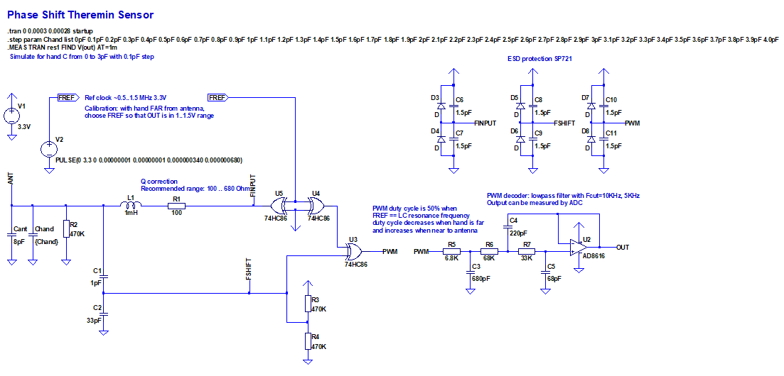
I didn't find easy way to get timer resolution better than 150MHz on Teensy 4.0.
After simulation, I see that measurement of oscillator frequency on Teensy 4.0 would not give enough precision (at list w/o significant averaging == latency). Sensor sensitivity is one of main reasons why FPGA is usefult for digital theremin design.

But I'm going to try another solution - phase shift based sensor.

Reference clock is passed to LC tank input, L output is phase shifted depending on difference between ref clock frequency and LC resonant frequency.
When LC resonance matches, phase shift is PI/4. If does not match, shift is moving to 0 or PI/2, proportional to tan(x). Frequencies near resonance have good sensitivity (bigger phase shift), far from resonance phase shifts are being "compressed". Compression depends on LC tank Q.
Reference frequency and LC Q should be tuned to have good sensitivity for hand distances far from antenna.

Phase shift between LC tank input and output is being converted to PWM signal using XOR (74AC86). Frequency of PWM will be Fref*2, duty cycle = 50% when LC resonant = Fref,  Fref, >50% if LC resonant frequency is lower than Fref.

According to LTSpice model, we can have 0.5..1pF antenna C change range as ~50% of output values range, while "compressing" other 1-2pF corresponding to closer hand distances to smaller output range.

LTSpice model may be found on Github


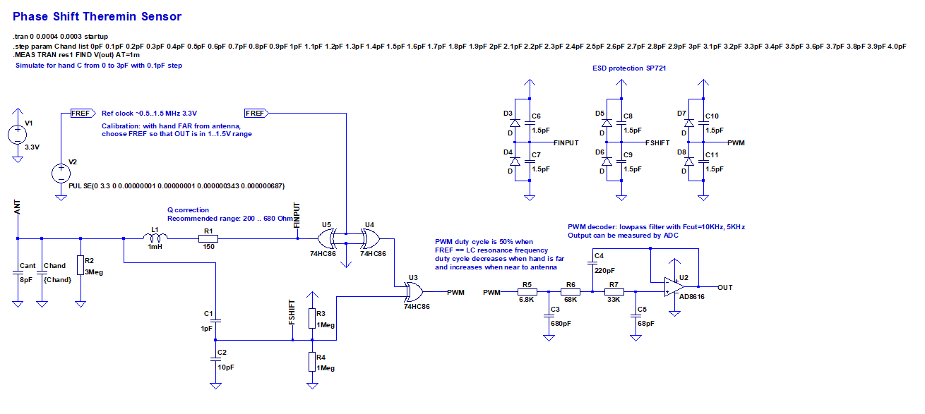
PWM should be filtered by LP filter (sallen-key 3rd order filter on rail-to-rail opamp with Fcut=10000Hz seems to be ok).

Simulation results (for different C_hand 0 pF.. 4pF with step 0.1pF) for R1=150 Ohm

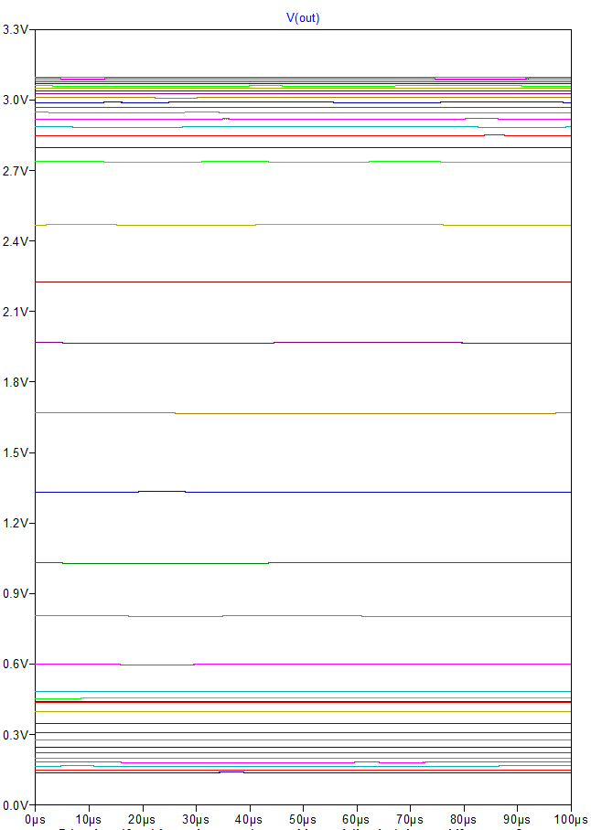
There are artifacts due to FSHIFT exceeding 0..3.3V range - visible on output values near edges.

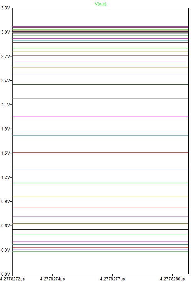
Tuned version: R2=470K between antenna and ground added, R1=100. Now output values are properly distributed and provide correct values even far from center.
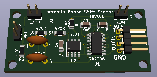
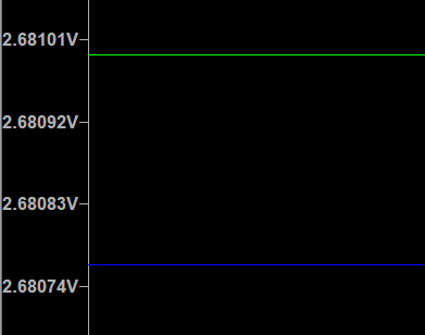
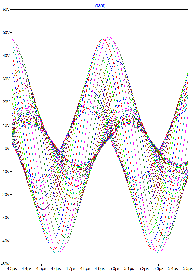
Voltage on ANTENNA

Output value of LP filter can be measured by MCU ACD.

Teensy 4.0 has 2-channel 12-bit 1Msps ACD , able to measure two inputs (muxed from 10 available pins) simultaneously.
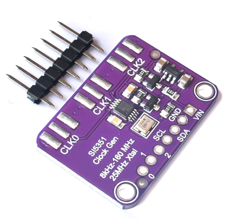
Fref may be generated on any pin using PWM or timer as divided 150MHz/div. Resulting step of possible frequencies is smooth enough to be able tuning Fref to match close enough to LC resonance (should be a bit lower than LC freq for hand far from antenna).
According to simulation, C_hand and voltage from filter have tan() relation.

Let's assume that effective LP output for all hand distances will vary in range 0.25Vcc..0.75Vcc - it gives us 11 bits of data.

Teensy 4.0 ACD has hardware averaging capabilities - it can make N measures, and sum them (N can be 4,8,16,32).
This gives us additional 5 bits of data for single x32 averaging measure - 16 bits in total.
It's possible to do this measure several times per sample (introduced latency is < Fsample). Additional averaging may give even more data bits (introducing some latency).

I'm checking capabilities of Teensy 4.0 audio interface. 
Already checked that 24 bits instead of 16 and 48KHz instead of 44100 is possible.
It looks like it's possible to have I2S output one sample per interrupt (instead of DMA transfer of audio data frames). CPU speed is high enough to consider interrupt cost as acceptable (e.g. if it's <1%). 
If it's possible - even oldtemecula could not say his usual speech about latency.


So, sensor would require only 4 pins from Teensy 4.0 MCU - 2 for pitch and volume reference frequency, and 2 ACD inputs.

Posted: 10/10/2019 2:57:44 PM
dewster

From: Northern NJ, USA

Joined: 2/17/2012

Interesting!  I've seen this on the scope hundreds of times, and thought it could be used to make a simple Theremin axis.  If I'm understanding correctly, you're setting a fixed "reference" drive frequency to "calibrate" the axis, with the maximum "gain" in the far field?

I see that you're moderating the Q via R1 and R2, I think this is probably necessary with air core coils, as you need the resonance region spread out somewhat for this approach.  The phase gain of LC Q in a PLL feedback loop is Q/pi (I worked through the math of this sometime back because total PLL loop gain needs to be less than 1 for stability).

Placing resonance in the far field gives best sensitivity there, then you compensate near mid and near fields with trig functions, then do a final linearization.

One possible issue is there is a double whammy going on with antenna voltage swing: as the hand approaches a normal oscillator antenna, the resistance of the human body damps the oscillations and you end up with a significant lowering of amplitude (if you are relying on Q to get large voltage swing).  Here you would see a further major reduction in swing due to the off-resonance drive.  Hum coupling is worse in the near field, not sure if a significantly lowered swing here would make things significantly worse in that regard or not.

Another possibility is an analog PLL with the loop voltage sent to ADC, but that might be more difficult to build and trim.  At least it wouldn't suffer from the double whammy issue.  As you note, FPGAs really excel at this micro timing stuff.

I'm kind of surprised you can use an op-amp filter at these frequencies?  Though that looks like a nice op-amp you picked.

This is kind of an "upside down" version of the volume side of most analog Theremins?  IIRC someone showed up here years ago with an analog Theremin design that worked somewhat like this on both axes - can't find a link to it but it was basically small boxes on large vertical pole, with a horizontal pole coming out of the side.

Posted: 10/10/2019 4:49:49 PM
Buggins

From: Porto, Portugal

Joined: 3/16/2017

Interesting!  I've seen this on the scope hundreds of times, and thought it could be used to make a simple Theremin axis.  If I'm understanding correctly, you're setting a fixed "reference" drive frequency to "calibrate" the axis, with the maximum "gain" in the far field?

During calibration, hand is far from antenna (or player far away from device). MCU tries different reference frequencies, finding one with output near middle of range or a bit lower (e.g. for recent simulation results, it should be between 0.9 and 1.5 volts). It gives best sensitivity on far hand distances.
When hand approaches antenna, output voltage from LP filter will raise, reducing voltage/C_delta sensitivity by distances near antenna.


I see that you're moderating the Q via R1 and R2, I think this is probably necessary with air core coils, as you need the resonance region spread out somewhat for this approach. 

R1,R2,C2 should be selected to meet two conditions:
Optimal Q - have good sensitivity for both far and close hand distances while having big enought output voltage range for different positions
Signal on XOR input from LC tank should be kept in range 0..3.3V, but near to 3.3V for max (resonance) amplitude.

The phase gain of LC Q in a PLL feedback loop is Q/pi (I worked through the math of this sometime back because total PLL loop gain needs to be less than 1 for stability).Placing resonance in the far field gives best sensitivity there, then you compensate near mid and near fields with trig functions, then do a final linearization.One possible issue is there is a double whammy going on with antenna voltage swing: as the hand approaches a normal oscillator antenna, the resistance of the human body damps the oscillations and you end up with a significant lowering of amplitude (if you are relying on Q to get large voltage swing).  Here you would see a further major reduction in swing due to the off-resonance drive.  Hum coupling is worse in the near field, not sure if a significantly lowered swing here would make things significantly worse in that regard or not.

Another possibility is an analog PLL with the loop voltage sent to ADC, but that might be more difficult to build and trim.  At least it wouldn't suffer from the double whammy issue. 
As you note, FPGAs really excel at this micro timing stuff.

I hope event with damped amplitude, signal on XOR input will be enough to switch its state.


I'm kind of surprised you can use an op-amp filter at these frequencies?  Though that looks like a nice op-amp you picked.

There is a good site with online filter calculators
opamp - is just one of few rail-to-rail fast enough opamps available in LTSpice library.


This is kind of an "upside down" version of the volume side of most analog Theremins? 
IIRC someone showed up here years ago with an analog Theremin design that worked somewhat like this on both axes - can't find a link to it but it was basically small boxes on large vertical pole, with a horizontal pole coming out of the side.

Usually in analog theremin volume antenna cirquit is controlled by amplitude detection, not phase shift.

If your design may be considered as double pitch antennas, my one looks like double "analog volume" style antennas.

Actually, if cirquit may be tuned properly to have "linearized" hand distance to note or hand distance to frequency relation - it may control analog synthesizer VCO (or send volt-per-octave control signal to synthesizer).

Posted: 10/14/2019 5:12:57 PM
Buggins

From: Porto, Portugal

Joined: 3/16/2017

Designed phase shift sensor PCB: KiCad project

Just a nice 3d render:

I'm planning to put sensor PCBs in separate boxes together with inductors near antennas. Sensor boards will be connected to main PCB with 4-wire connectors. I hope PWM signal passed through 20cm cable would not catch a lot of noise.

Work on main PCB is in progress.

Posted: 10/14/2019 11:09:55 PM
Thierry

From: Colmar, France

Joined: 12/31/2007

One problem I see is that in opposite to your simulation, the hand capacitance falls to roughly 1/3.5 for each 10 cm more distance (measured with a rod, but a loop will be similar), so realistic simulation steps would be 1.5pF, 0.43pF, 0.12pF, 0.035pF for 1, 11, 21, and 31 cm. Do you think you'll still have enough precision/resolution after linearizing that? I'd guess that driving the phase discriminator in the more flat region of the curve while having the max dV/dphi without hand could help.

The other problem is that the iMXRT1062 ADCs are delta-sigma converters with a nominal resolution of 12, but with only 10usable bits, the rest is noise. 
BTW, oversampling and averaging by factor n does only increase the effective resolution by sqrt(n). 4 times oversampling gives 2 times better resolution which corresponds just to one more bit. 32x averaging will give just 2.5 useful bits.

But in general, the phase shifting on fixed frequency approach looks basically promising. The tVox tour theremin uses it on the volume side in discrete mixed CMOS and analog technology to get the volume CV for the VCA. The only problem is that the pitch field of a nearby Etherwave Pro fully mutes the tVox, although the EPro radiates on 282kHz and the tVox volume oscillator drives the loop at 305kHz. Obviously close enough.

Posted: 10/15/2019 1:54:15 AM
dewster

From: Northern NJ, USA

Joined: 2/17/2012

"But in general, the phase shifting on fixed frequency approach looks basically promising. The tVox tour theremin uses it on the volume side in discrete mixed CMOS and analog technology to get the volume CV for the VCA. The only problem is that the pitch field of a nearby Etherwave Pro fully mutes the tVox, although the EPro radiates on 282kHz and the tVox volume oscillator drives the loop at 305kHz. Obviously close enough."  - Theirry

Fascinating!  I imagine the Q needs to be lowered somewhat in order to give a decent numerical range for a given hand movement range, and this broadening out of the resonance makes it more succeptible to closely placed interferers.

I still think a quadrature PLL approach is the best of most worlds.  Q can be sky high which gives really big voltage swing at the antenna, as well as good selectivity / rejection of interferers.  And that it can be done digitally without D/A or A/D is a big bonus.

Posted: 10/15/2019 8:48:44 AM
Buggins

From: Porto, Portugal

Joined: 3/16/2017

One problem I see is that in opposite to your simulation, the hand capacitance falls to roughly 1/3.5 for each 10 cm more distance (measured with a rod, but a loop will be similar), so realistic simulation steps would be 1.5pF, 0.43pF, 0.12pF, 0.035pF for 1, 11, 21, and 31 cm. Do you think you'll still have enough precision/resolution after linearizing that? I'd guess that driving the phase discriminator in the more flat region of the curve while having the max dV/dphi without hand could help.The other problem is that the iMXRT1062 ADCs are delta-sigma converters with a nominal resolution of 12, but with only 10usable bits, the rest is noise. BTW, oversampling and averaging by factor n does only increase the effective resolution by sqrt(n). 4 times oversampling gives 2 times better resolution which corresponds just to one more bit. 32x averaging will give just 2.5 useful bits.But in general, the phase shifting on fixed frequency approach looks basically promising. The tVox tour theremin uses it on the volume side in discrete mixed CMOS and analog technology to get the volume CV for the VCA. The only problem is that the pitch field of a nearby Etherwave Pro fully mutes the tVox, although the EPro radiates on 282kHz and the tVox volume oscillator drives the loop at 305kHz. Obviously close enough.

So, +10cm distance eats 1.8 bits of precision. It's expected.
But what is unexpected for me is that averaging xK gives sqrt(log2(k)) instead of log2(k) bits. Are you sure? I was expecting that x32 oversampling should give 5 bits, not 2.5
In this case, 12/11/10 bits of Teensy 4.0 ADC seems not enough for higher distances.
It looks like external high precision ADC is needed.
There are ADS1256 8-channel 24-bit 30Ksps ADC modules (~$16) available on aliexpress.
According to ADS1256 datasheet, there are 17 noise free bits available for 30ksps sampling.
It can measure inputs up to 3V, so it makes sense to invert PWM signal and change VCC from 3.3 to 5V - this would give ~2.5..3V for hand far from antenna, decreasing when hand approaches antenna. As well, increasing of PWM signal V from 3.3 to 5V should reduce noise.

Teensy 4.0 capabilities to generate reference frequency might be not enough (it can give 150MHz/k output). Although, with lower LC frequencies (e.g. 500KHz instead of 1500KHz, adjusting possibility of reference frequency is good enough.
In case if finer Fref setting is needed, external clock generator may be used, e.g. module on SI5351.


BTW, Moog Theremini repeats pitch changes of Etherwave on distance 3..4 meters.

Posted: 10/15/2019 11:53:48 AM
Buggins

From: Porto, Portugal

Joined: 3/16/2017

I've modified model to use 5V, a bit bigger Q, inverse PWM (output decreases when hand is closer to antenna). Reference clock is tuned to have output value near 2.5..3V for far hand range.  First 0.1pF change covers about 1/6 of working range. 

Assuming working range of ADC is 3V and has 17bits w/o noise.
For most sensitive range of 0.1pF, we will have 17-3 = 14 bits for 0.1pF

For 10cm ranges: 
55 cm from antenna we have 8 bits of data
65 cm - 6.5 bits
75 cm - 5 bits
85 cm - 3 bits

Checking on simulation (Q is increased a bit, LP filter cutoff = 3KHz):
C_hand steps are equivalent to linear distance steps:


Code:
.step param Chand list 1.5pF 0.43pF 0.12pF 0.035pF 0.0102pF 0.002977pF 0.000868pF 0.000253pF 0.000073875773pF 0.000021547100pF
//                      1cm  11cm    21cm  31cm    41cm      51cm      61cm      71cm        81cm              91cm

Bottom line near 0.3v is 1cm distance, second line 0.9V - 11cm distance, 2V - 21cm etc

Zooming in - bottom line is 21cm distance

More zoom, bottom line is 41cm distance

Max zoom - 81cm and 91cm distances

Between 81cm and 91cm, output V varies by 0.15mV
17 bit of noise free ADC value for 3V range gives 0.0234mV per LSB
0.15/0.0234 = 6 LSB values, ~2.5bits
Of course, it's too little but probably additional averaging may help.

61cm: 2.6768
  = 3mv    294*MSB,    ~8 bits
71cm: 2.67974
  = 1mv    43*MSB,      ~5.5 bits
81cm: 2.68075


BTW, what is usual max playable distance for theremin? A believe it's ~70cm

Posted: 10/15/2019 1:35:36 PM
dewster

From: Northern NJ, USA

Joined: 2/17/2012

"But what is unexpected for me is that averaging xK gives sqrt(log2(k)) instead of log2(k) bits. Are you sure? I was expecting that x32 oversampling should give 5 bits, not 2.5"  - Buggins

What Thierry is describing is what I've seen: you only get half the bit resolution increase you might naively expect from averaging (or first order filtering).  If you think about it, when you average a bunch of coin tosses the average can "move around" due to the randomness of the elements in the combined distribution.  Seen from a filtering perspective, the averaging attenuates high frequency noise, but low frequency noise can still get through largely unattenuated.  Make the aggregate larger and you move the pole of the first order filter lower.  Averaging is equivalent to a first order CIC or boxcar filter, which is very similar to a first order IIR lowpass filter.  All of this stuff could have been easily explained to me in college, not sure why it wasn't (professors love their maths too much).

[EDIT] You may not want to average all the noise out before you measure the signal.  Depending on the thing doing the measuring (quality of the A/D converter), the noise can actually increase the resolution of the measurement, and then you can average in the digital domain to get higher resolution (this is ad-hoc dithering).  But that can make you highly dependent on the characteristics of the noise (you don't want the noise amplitude to be smaller than one bit of the A/D resolution for any reasonable length of time, otherwise the stepping may become apparent to the player).

[EDIT2] The expected resolution increase with averaging / filtering can help you size the width of your digital filters.  If the averaging / filtering will only give you, say, an 8 bit increase, then if you are having trouble getting a 16 bit wider filter to run at speed, then why not truncate it to something smaller?  This is balancing truncation noise with system noise, and it always happens to some degree (particularly inside filters) whether you are aware of it or not.

[EDIT3] First order filtering or averaging isn't the holy grail or the best you can do.  Higher order averaging (CIC filtering) or higher order filtering (multi-pole IIR, or I suppose FIR though I would avoid them in these applications) can give you better SNR due to the increased HF attenuation, though of course only to a point.

Posted: 10/15/2019 2:20:32 PM
Buggins

From: Porto, Portugal

Joined: 3/16/2017

LP filter should be tuned to have output varying in range ~ ADC significant bit to improve averaging results with dithering.

So far, I've ordered ADS1256 (ADC) board and si5351 (PLL clock gen) board.

You must be logged in to post a reply. Please log in or register for a new account.