Teensy 4.0 600MHz ARM Cortex M-7 MCU - ideal for digital MCU based theremin?

Posted: 12/18/2021 5:33:31 AM
Buggins

From: Porto, Portugal

Joined: 3/16/2017


Vadim, max clock frequency for capture timer (approx.)?
-- ILYA

In Lichee Tang Nano GW1N-LV1QN48C6/I5 has max PLL frequency 450MHz. If clocked from I2S MCLK signal 12.288MHz, with integer multiplier max frequency is 442.368MHz
This frequency used as DDR clock gives 884.736MHz sampling rate (resolution). With DDR x8 serdes, FPGA may process 8-bit deserialized data at 110.592MHz.
OSER8 DDR serializer takes 8 bits of data at DDRCLK/4 clock (110.592MHz), and shifts them out at DDRCLK*2 rate (884.736MHz).
ISER8 DDR deserializer shifts in serial data sampled at at DDRCLK*2 rate (884.736MHz) and provides 8 bits of data at DDRCLK/4 clock (110.592MHz).
I've tried to write DCO with OSER8 LVCMOS33D differential output working at these rates.
No timing violations according to place&route timing analysis.

There is a bit faster gw1n - uv (high performance) vs lv (low power). uw-6 has 500MHz max PLL frequency, and 983.04MHz sampling rate with 491.52MHz DDR clock.
But there is no such cheap small board like tang nano on this chip - you have to solder qfn48 with 0.4mm pitch yourself.

Similar Lattice FPGA machxo2 -4 speed grade based TinyFPGA AX2 board has 269MHz max DDR clock (rounded to MCLK - 258MHz), and would have sampling rate 516MHz - almost twice lower.
As well, TinyFPGA AX2 is out of stock everywhere, while tang nano are available, at least on aliexpress.

Ideas - how to increase sampling rate even more:

Utilize i/o delay blocks, use several pins to send or receive the same signal, with different delay.
For output, use two DDR outputs with delay difference corresponding to half of DDR sampling rate. Odd 8 bits of 16-bit parallel value should be routed to one pin, and even 8 bits - to another. Connect together via resistors - and you will have better edge resolution - with 1.65V in DDR half period where two inputs have different values.
For input, put input signal on pair of inputs, use two IDDR inputs with delay block, having DDR sampling rate / 2 phase difference.
Mix two 8-bit values from deserializer to 16 (odd/even).
This approach can be scaled. Doubling of number of inputs / outputs for the same signal may give double resolution.
E.g. quad inputs with different delay give quad resolution (3.5GHz)


Posted: 12/18/2021 1:59:00 PM
dewster

From: Northern NJ, USA

Joined: 2/17/2012

"In Lichee Tang Nano GW1N-LV1QN48C6/I5 has max PLL frequency 450MHz. If clocked from I2S MCLK signal 12.288MHz, with integer multiplier max frequency is 442.368MHz.  This frequency used as DDR clock gives 884.736MHz sampling rate (resolution)."  - Buggins

Sampling at ~400MHz is entirely sufficient, anything higher than that is gravy - good gravy!

I don't know, but I might worry a little about jacking up an external 12MHz 40x to use as the logic clock.  If the internal PLL can condition it well I guess it would probably be OK.  A differential clock input would of course be best as it would reject common mode noise at the pins (bank I/O VCC often gets yanked around by the output pins).  A lot of digital Theremin work is minimizing internal interference (or the influence of it).

Vadim, have you considered UHF connectors instead of plumbing?  I think they look more professional, are easier to connect / disconnect, and they insulate the antenna lead from the mildly capacitive wooden case.

Try to keep the coil (particularly the sensitive end) maybe 30mm away minimum from significant metal, it can act like a shorted winding and hurt Q.

Posted: 12/20/2021 2:59:02 PM
Buggins

From: Porto, Portugal

Joined: 3/16/2017


Sampling at ~400MHz is entirely sufficient, anything higher than that is gravy - good gravy!

Ok, so x2 higher sampling frequency should be fine.

I don't know, but I might worry a little about jacking up an external 12MHz 40x to use as the logic clock.  If the internal PLL can condition it well I guess it would probably be OK.  A differential clock input would of course be best as it would reject common mode noise at the pins (bank I/O VCC often gets yanked around by the output pins).  A lot of digital Theremin work is minimizing internal interference (or the influence of it).

Tang Nano FPGA board has internal 24MHz xtal. We can use it as PLL input to produce all clocks. 24MHz*9=432MHz (864MHz sampling rate, 108MHz FPGA processing clock). It's even divisible by 48KHz audio sample clock (x2250).


Vadim, have you considered UHF connectors instead of plumbing?  I think they look more professional, are easier to connect / disconnect, and they insulate the antenna lead from the mildly capacitive wooden case.

Not sure how do I mount antenna pipe on BNC or TNC connector.
Regarding influence of wood, what about considering acrylic laser cut?

Try to keep the coil (particularly the sensitive end) maybe 30mm away minimum from significant metal, it can act like a shorted winding and hurt Q.

Tried to change placement of coils a bit.
For volume sensor, we should not worry a lot. High sensitivity is not required there.

I've reduced length of pitch inductor, and now it has bigger distance from antenna mount.


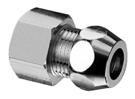
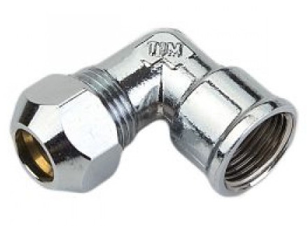
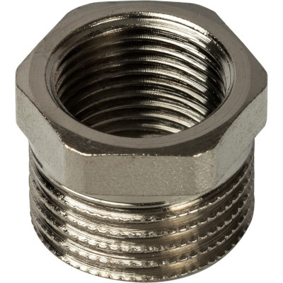
To increase distance from coils to massive plumbing antenna mount, we can use different fittings.

Posted: 12/24/2021 4:53:18 PM
Buggins

From: Porto, Portugal

Joined: 3/16/2017

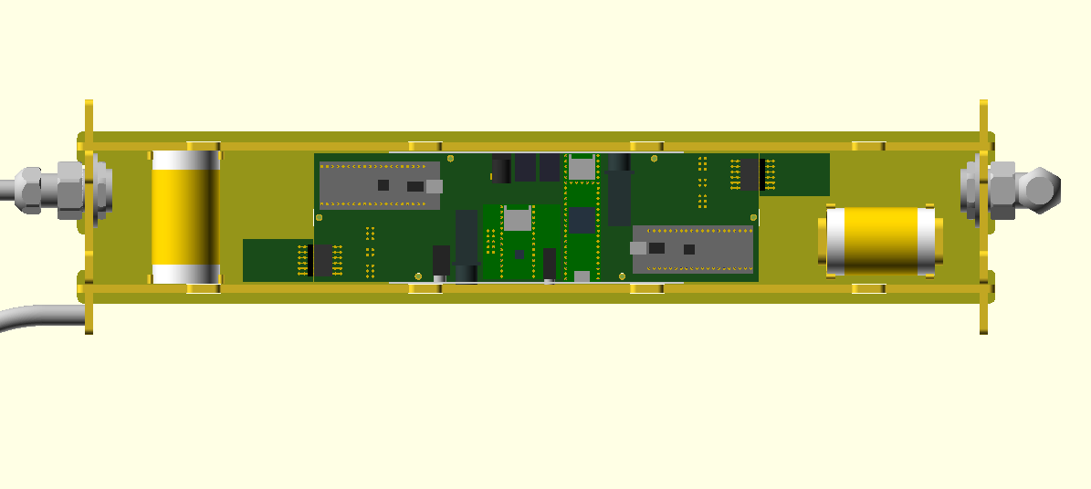
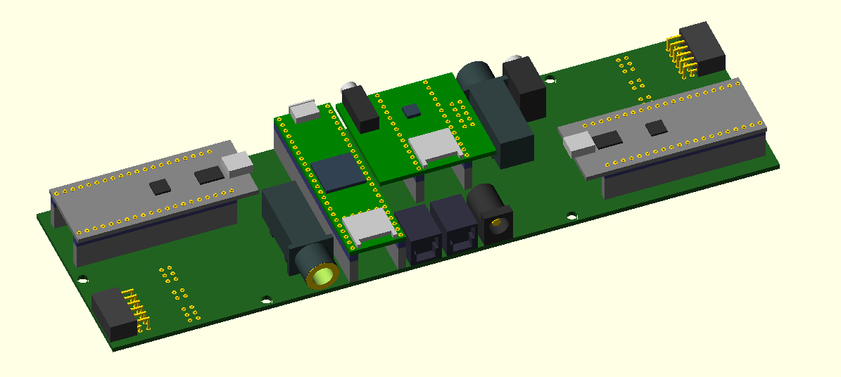
Updated cabinet model in OpenSCAD. Almost finished.


Tried to optimize inductors placement - keep far enough from antenna mounts.

PCB now has all connectors modelled.

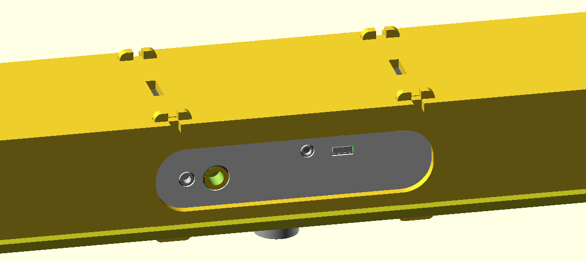
Front panel connectors: Line In 3.5mm audio jack, Line Out 6.35mm audio jack, Phones Out 3.5mm audio jack, Micro USB

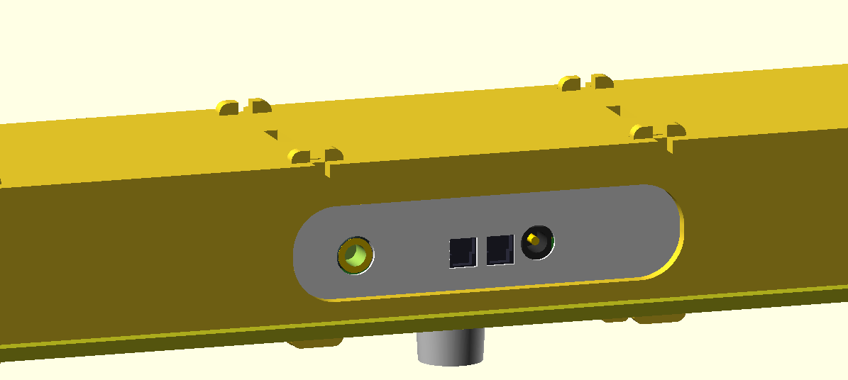
Back panel connectors: Expression Pedal 6.35mm audio jack, fiber S/PDIF In, fiber S/PDIF Out, Power In +5V barrel jack.


It would be useful to add grounding connector. But I'm not sure what type of connector better fits for grounding.
Banana? I cannot find pcb mounted banana. 

Posted: 12/28/2021 12:53:52 PM
Buggins

From: Porto, Portugal

Joined: 3/16/2017


Wow! Upgraded KiCAD to fresh 6.0 release. A lot of improvements!

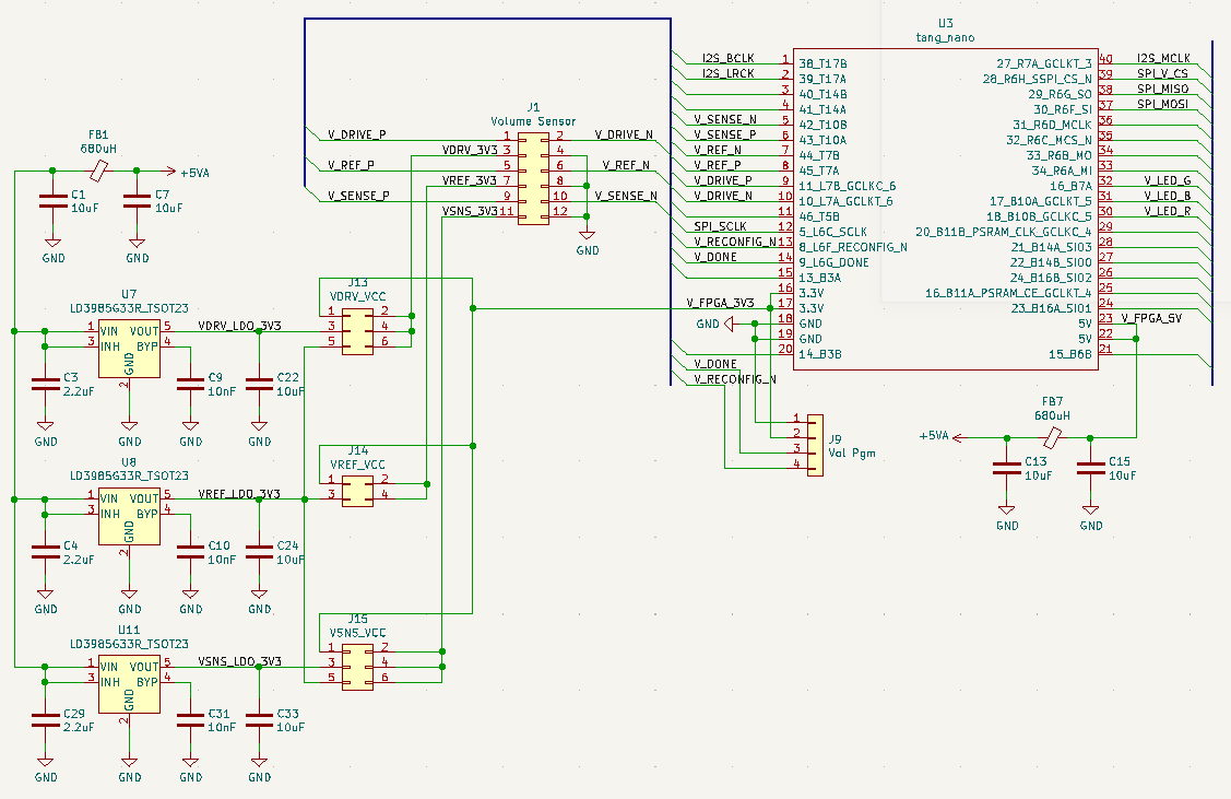
Connection of tang nano FPGA board and sensor analog part.
Drive, feedback and sense signals are routed as differential pairs - LVCMOS33D.
Trying different sensor boards, we can decide if differential transmission of theremin sensor signals
could provide any benefit. Single ended connection may be used - if i/o mode in FPGA constraints set to non-differential for the pins.

For experiments with power supply of analog part, there are three optional regulators: separate for drive, feedback and sense.
There is a concern from Eric, that current sensing sensor with zero working phase shift is sensitive to drive/feedback to sensing IC interference via power supply.
With jumpers, for each of 3 signals we can choose one of power supply options:
1) Use 3.3V provided by FPGA board pins - left i/o bank 3.3V regulator. Drive output is connected to this bank. Feedback and sense inputs are connected to another bank, powered from separate regulator not available via pin.
2) Use separate regulator soldered on board.
3) Share regulator with Feedback channel.
Based on experiment results, we will solder 0-3 regulators per sensor on main board.
W/o regulators, main board will consist of board connections pin sockets, audio i/o connectors, sensor connectors, and wires between their pins. No active components.

I have got some questions.

Does it make sense to put a few ferrites to minimize noise between boards via power supply?
How do I choose L and C for such filters?

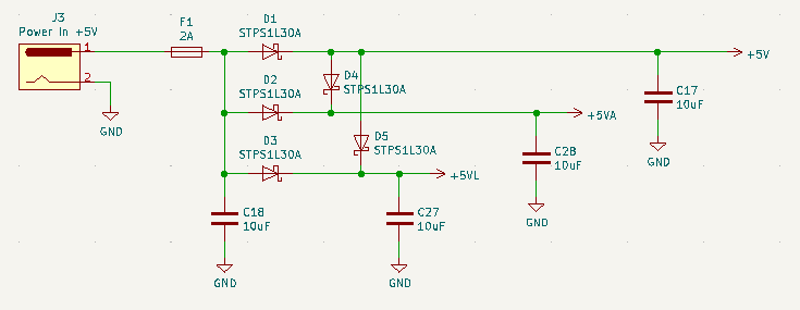
Teensy will be connected to tablet via micro USB - and powered from it. USB VCOM (+5V) is available on teensy board +5V pin.
Board has barrel jack, +5V Power Supply input.
Tang Nano FPGAs have USB type C connectors for programming.
There may be some issues when several power supplies connected to board at the same time.
For Teensy board, there are recommendations to cut usb to 5v pin wire and solder diode. Connect external +5V via diode, too.
It will effectively reduce +5V line voltage by 0.3..0.4V
FPGA +5V pin is connected directly to USB connector pin. It makes sense to put diode between main +5V line and FPGA 5V pin.
Or two diodes - one from Teensy +5V pin, second from barrel jack connector.
In this case, when powered from teensy USB connector only (from tablet), fpga will have power supply +5V from USB connected via two diodes - 0.6..08V less (4.2..4.4V instead of 5).
With two diodes per fpga power supply, when main board is powered via power jack, fpga board will receive supply via single diode (4.6..4.7V).
Any suggestions? Isn't it an overkill?


+5V wire above is Teensy +5V pin (connected directly or via diode to micro USB VCOM).
+5VA is volume sensor +5V input
+5VL is pitch sensor +5V input

As well, does someone have an idea how to implement grounding connector?


So far, writing Android application - UI and control for theremin.
Connected teensy to Samsung tablet using USB type C male to USB micro male cable.
Now my application receives notification when teensy USB Serial is connected or disconnected.
Some more effort is required to implement usb serial interface data transmission.


Posted: 12/29/2021 11:14:39 AM
dewster

From: Northern NJ, USA

Joined: 2/17/2012

"Wow! Upgraded KiCAD to fresh 6.0 release. A lot of improvements!"  - Buggins

Aieee!  I was waiting for that (reason to procrastinate) but didn't think it would happen until early next year.

"There is a concern from Eric, that current sensing sensor with zero working phase shift is sensitive to drive/feedback to sensing IC interference via power supply."

This is more of an internal IC thing for my AFE.  Can't isolate the hex inverters from each other inside the IC package.  Using individual tinylogic parts could certainly help.  But the coil resonance quadrature seems to spaces these things out fairly well.

I guess I still don't see how in-phase feedback can work with an XOR type gate phase detector, it seems to demand edge detection to generate an error term (the sign of the error seems like it would be ambiguous otherwise)?

"With jumpers, for each of 3 signals we can choose one of power supply options:"

If the I/O is differential then it doesn't seem like the supply is very critical.  For the interface.  I think it's more critical for the analog on the sensor board, which is why my AFE has a regulator.

"Does it make sense to put a few ferrites to minimize noise between boards via power supply?"

Putting a regulator on the sensor board should help isolate things?

"There may be some issues when several power supplies connected to board at the same time."

Do you mean power sequencing?  I get around this by sticking a ~100 ohm series resistor located at each driver, which also improves signal integrity.

"With two diodes per fpga power supply, when main board is powered via power jack, fpga board will receive supply via single diode (4.6..4.7V).
Any suggestions? Isn't it an overkill?"

Not saying you should go this route, but my stuff is powered via thin wires from the USB serial dongle so it's generally plagued with low voltage issues, and diodes can only make that worse.  When you draw 0.5A or so from any USB port you find out how flaky the USB power connection is in every PC, extension cable, dongle, etc.  Even a power switch can have significant voltage drop when it's switching 5V with significant current (my FPGA is a power hog).

"As well, does someone have an idea how to implement grounding connector?"

Just a stud of some sort that folks can connect an alligator clip to?  It doesn't have to be fancy at all, the lower the tech here the better IMO.

Posted: 1/6/2022 2:07:17 PM
Buggins

From: Porto, Portugal

Joined: 3/16/2017


I guess I still don't see how in-phase feedback can work with an XOR type gate phase detector, it seems to demand edge detection to generate an error term (the sign of the error seems like it would be ambiguous otherwise)?
-- dewster


It's pretty simple.

With single bit inputs:

Code:
input wire A;
 input wire B;
 output reg [9:0] PHASE;


We have single bit state and phase error accumulator (number of bits depends on sampling frequency and lowest supported oscillator frequency).


Code:
reg state;
 reg [9:0] error;
 reg [9:0] prev_error;


When both inputs are equal (00 or 11) and not equal to current state, we will update state to this value.
When inputs are different, we will add +1 or -1 to error accumulator, taking into account state (state 1 inverts error sign).
On state change, pass error accumulator value to output and reset error accumulator.
It makes sense to hold two recent error values (from two edges) and average them - to reduce non-50% duty cycle issues.


Code:
always @(posedge CLK) begin
	if (RESET) begin
		state = 0;
		error = 0;
		prev_error = 0;
		PHASE = 0;
	end else begin
	    if (A == B && A != state) begin
			// changing state
			PHASE <= error + prev_error;
			prev_error <= error;
			error <= 0;
		end else if (A != B) begin
			error <= error + (
				(A == state) ? -1 : 1; // not sure about sign, probably need to swap
			);
		end
	end
end


In real implementation, we will have 8-bit input values (sequence of 8 samples from x8 input ddr deserializer).
With this approach, there are no issues like dead zones of analog flipflop zero phase detectors.

The only disadvantage comparing to 90 degrees phase XOR based detector, is bigger complexity of processing. But I expect the cost of zero phase comparing to 90 deg phase detector is 30-50LUTs.


If the I/O is differential then it doesn't seem like the supply is very critical.  For the interface.  I think it's more critical for the analog on the sensor board, which is why my AFE has a regulator.
Putting a regulator on the sensor board should help isolate things?
-- dewster


Even in single ended version, there will be separate tiny logic ICs for each signal. 

Ok, I'll just remove ferrite filters from my schematic.


"There may be some issues when several power supplies connected to board at the same time."
Do you mean power sequencing?  I get around this by sticking a ~100 ohm series resistor located at each driver, which also improves signal integrity.
-- dewster


Teensy MCU board will be connected to tablet using USB cable - so USB power is connected to +5V pin of teensy board.
There is an additional barrel jack - external +5V.

When external +5V is connected to tablet's USB VCOM working in OTG mode, it seems to be unsafe (magic smoke from tablet?)

On tang nano FPGA boards, +5V pin is connected directly to their own USB type-c power pins.
If you connected usb to fpga for flashing of configuration update, and main board is powered from either tablet or external +5V jack, something might go wrong.
I believe, some protective diodes are required. Just not sure if 4.4..4.7V is enough for powering of teensy and fpga boards.

"As well, does someone have an idea how to implement grounding connector?"
Just a stud of some sort that folks can connect an alligator clip to?  It doesn't have to be fancy at all, the lower the tech here the better IMO.
-- dewster


I tried to find some banana jack with pcb mounting, but can see only panel or wire mounting banana connectors.


Posted: 1/9/2022 2:11:32 PM
dewster

From: Northern NJ, USA

Joined: 2/17/2012

Vadim, I don't have a SV simulator handy anymore, but I looked at your phase detector on paper and think I understand it. I believe you left out the actual assignment of the state variable, which I assume happens when (A == B && A != state).

Consider the scenario where a glitching B is centered on A (without error averaging):

A=0, B=0 : state=0, error=0
A=1, B=1 : state=1, error=0
A=1, B=0 : state=1, error=-1
A=1, B=1 : state=1, error=0
A=1, B=0 : state=1, error=-1
A=1, B=1 : state=1, error=0
A=0, B=0 : state=0, error=0

The phase error is -2 but it should be zero.

I'm not saying this is a fatal flaw, but an XOR quadrature detector doesn't do this, and any systematic error could potentially be a problem.

There's also the simultaneous digital switching on the analog side that I would worry about, which quadrature also neatly sidesteps.

The main downside of the C divider approach is the manual component scaling required to make it work optimally, but this doesn't seem to be very onerous as long as the surface area of the antenna (i.e. intrinsic C) remains within reasonable bounds.  And attenuating the antenna signal by 100pF:1.5pF (1/67) should similarly attenuate any interference by that same ratio, something I hadn't really thought about (though of course it all gets amplified back up to square it).

Also, in my DPLL the phase accumulator operates continuously, and the result is presented to the NCO on every clock.  The XOR output is a square wave, which gets converted to a triangle wave in the accumulator, but the frequency is quite high and amplitude is quite low, and the loop cutoff is set very low, so it doesn't really affect the NCO duty cycle.  The 48kHz triangular dither is also applied continuously, which works really well.  The resulting NCO input value is used as output, after it is continuously filtered (1st order LPF to sample at 1:2 rate, followed by 4th order LPF working at 1/2 rate) and finally sampled at 48kHz synchronous to the dither, which effectively kills any instantaneous dither offset.  The whole thing turned out much simpler than I expected, and can reliably lock over a very wide frequency range (which I limit mainly to reduce the hunting period to speed up locking).

Posted: 1/10/2022 7:28:06 AM
Buggins

From: Porto, Portugal

Joined: 3/16/2017


Vadim, I don't have a SV simulator handy anymore, but I looked at your phase detector on paper and think I understand it. I believe you left out the actual assignment of the state variable, which I assume happens when (A == B && A != state).
-- dewster

Yes, I missed state update. I just typed this code in text editor, it's not a copy/paste from real code.


The phase error is -2 but it should be zero.
I'm not saying this is a fatal flaw, but an XOR quadrature detector doesn't do this, and any systematic error could potentially be a problem.
-- dewster

Such cases may appear either when drive frequency is being changed too fast, or when connection between FPGA and analog front end is noisy.
I believe, when drive frequency varies slowly, no such issues should appear.
And, of course, when phase is locked, sense signal should not have transitions except twice per signal period.


There's also the simultaneous digital switching on the analog side that I would worry about, which quadrature also neatly sidesteps.
-- dewster

I hope differential I/O, regulators, and decoupling caps should minimize this issue.

The main downside of the C divider approach is the manual component scaling required to make it work optimally, but this doesn't seem to be very onerous as long as the surface area of the antenna (i.e. intrinsic C) remains within reasonable bounds.  And attenuating the antenna signal by 100pF:1.5pF (1/67) should similarly attenuate any interference by that same ratio, something I hadn't really thought about (though of course it all gets amplified back up to square it).
-- dewster

When divider has too big ratio, or hand is close to antenna or touches antenna, signal as low amplitude. Some self-biasing is required to keep 50% duty cycle.
Since my AFE connector provides enough pins, I will be able to check different types of AFE, including both zero phase (current sensing) and 90-degrees phase (other side of inductor with capacitive divider).

Also, in my DPLL the phase accumulator operates continuously, and the result is presented to the NCO on every clock.  The XOR output is a square wave, which gets converted to a triangle wave in the accumulator, but the frequency is quite high and amplitude is quite low, and the loop cutoff is set very low, so it doesn't really affect the NCO duty cycle.  The 48kHz triangular dither is also applied continuously, which works really well.  The resulting NCO input value is used as output, after it is continuously filtered (1st order LPF to sample at 1:2 rate, followed by 4th order LPF working at 1/2 rate) and finally sampled at 48kHz synchronous to the dither, which effectively kills any instantaneous dither offset.  The whole thing turned out much simpler than I expected, and can reliably lock over a very wide frequency range (which I limit mainly to reduce the hunting period to speed up locking).
-- dewster

If you correct target DCO period every clock cycle, this value will look like sawtooth with long zero intervals.
In my plans, phase detector output (phase error) will be updated twice per drive signal period. It produces stairs-like output.
Phase error value will be added to target drive period value at every clock cycle. (DCO will take it twice per signal period - et every edge).
Waveform of accumulated phase error is a triangle.
To smooth detector output, phase detector output might be filtered by simple IIR filter before applying to drive frequency.
Dithering, if needed, can be applied pretty easy - by adding dither triangle to phase detector output.


Posted: 1/10/2022 2:00:11 PM
Buggins

From: Porto, Portugal

Joined: 3/16/2017

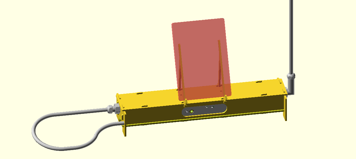
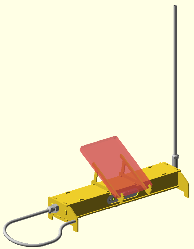
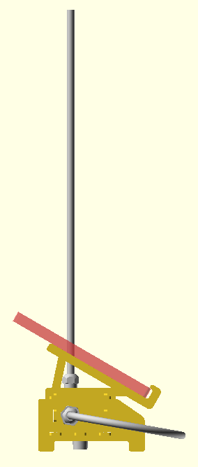
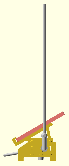
Teensy Theremin cabinet laser cut OpenSCAD design updated.

I've measured etherwave volume antenna mounting distance, and found that it's ~87mm vs 60mm I used in my design.
It would be nice to make cabinet compatible with etherwave antennas.
So, I've increased side length a bit.
As well, I've decreased tablet mount angle downto 30 degrees, and moved tablet towards player - to reduce tablet to pitch antenna capacitance.


Left view:

Right View:


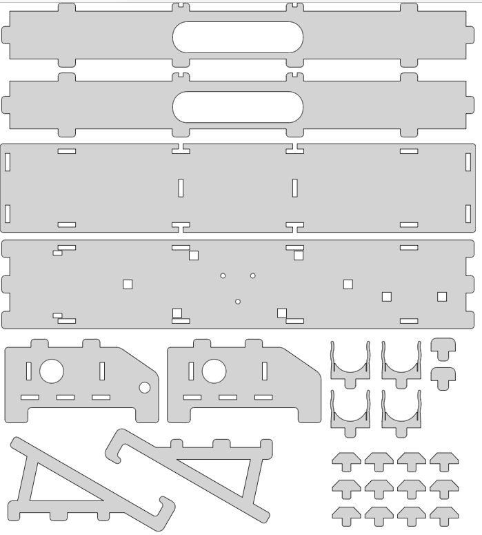
Tested export from OpenSCAD to 2D formats for laser cutting.
It seems like SVG should be ok.

Main sheet cutting layout (4mm acrylic or plywood sheet):


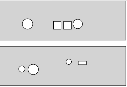
Front and rear panels (1mm acrylic sheet):

You must be logged in to post a reply. Please log in or register for a new account.