Inductor parameters in LTSpice and Coil64 output

Posted: 11/25/2019 9:47:35 AM
Buggins

From: Porto, Portugal

Joined: 3/16/2017

Hello,

What is proper way to specify coil parameters calculated by Coil64 in LTSpice inductor for best match between model and real schematic?

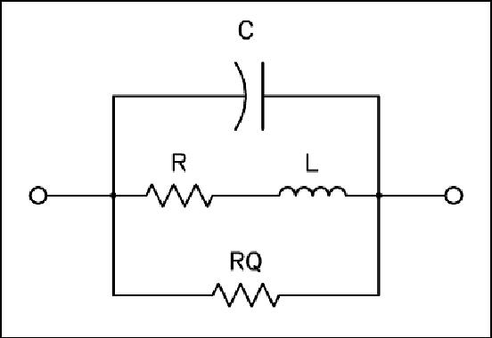
In LTSpice, there are

Code:
Inductance
Peak Current
Series Resistance
Parallel Resistance
Parallel Capacitance


Sample Coil64 output:

Code:
Coil64 v1.0.2 - One layer coil with round wire

Input:
Inductance L: 1,200 microH
Frequency f: 1.39 MHz
Former diameter D: 32 mm
Wire diameter d: 0.2 mm
Wire diameter with insulation k: 0.218 mm
Winding pitch p: 0.23 mm

Result:
Number of turns of the coil N = 325.085
Length of wire without leads lw = 32.904 m
Length of winding l = 74.970 mm
Weight of wire m = 9.19997 g
Reactance of the coil X = 10,480.353 Ohm

Self capacitance Cs = 1.343 pF
Coil self-resonance frequency Fsr = 2.550 MHz
Coil constructive Q-factor Q = 330
Loss resistance ESR = 31.759 Ohm

Additional results for parallel LC circuit at the working frequency:
=> Circuit capacitance: Ck = 9.583 pF
=> Characteristic impedance: ρ = 10,480 Ohm
=> Equivalent resistance: Re = 2,600.388 kOhm
=> Bandwidth: 3dBΔf = 5.602kHz


How do I fill LTSpice parameters properly?

Inductance - it's trivial
Peak Current - I'm usually putting 0.1 or 0.01 here
Series Resistance - is it Loss resistance ESR?
Parallel Resistance - is it Equivalent resistance? Should be megaohms here...
Parallel Capacitance - Self Capacitance?

Posted: 11/25/2019 5:37:32 PM
dewster

From: Northern NJ, USA

Joined: 2/17/2012

From: Modeling Non-Ideal Inductors in SPICE by Martin O’Hara Technical Manager, Newport Components, U.K. November 8 1993 [LINK]

Coil parasitic R is the series DC resistance.  I've read that you usually just double whatever Ohms you get with a DMM set to measure low resistances, which I suppose roughly makes up for things like skin effect.

Coil parasitic C can be calculated from the (measured) self-resonant frequency with the formula:

  C=1/(L*((2*pi*f)^2)). 

Coil parasitic RQ is the equivalent core loss parallel resistance and is calculated from the (measured) Q and (measured) self-resonant frequency with the formula:

  RQ=2*pi*f*L*Q.

The paper goes into higher order polynomial corrections, but I haven't investigated those myself.

Posted: 11/25/2019 7:06:30 PM
Buggins

From: Porto, Portugal

Joined: 3/16/2017

Thank you Dewster!

So, it looks like usage of Coil64 should look like:
1) Wind inductor
2) Measure actual L with LC meter
3) Measure actual R with Ohm meter
4) In LTSpice, specify L in model, find working frequency
5) In Coil64, enter frame diameter, wire diameter, wire+insulator diameter is autofilled, enter some coil-to-coil distance and winding length, specify initial working frequency. 
6) Try different coil-to-coil distance until L matched actual measured value (R should be close, too).
7) Set working frequency in Coil32
8) Calculate RQ and self capacitance in Coil32
9) Enter calculated RQ (Equivalent resistance) and self capacitance (or it should be cirquit capacitance on working frequency?) from Coil64 to LTSpice model
10) Check real working frequency
11) If working frequency has been change since last iteration, go to step 7
12) Profit

Posted: 11/25/2019 7:17:16 PM
dewster

From: Northern NJ, USA

Joined: 2/17/2012

You can measure the self resonance frequency and Q of your coil by placing the coil on something insulating like a plastic box far away from metal, driving one end of the coil with a function generator, and placing a scope probe near the other end (but not connected to it).  Q is calculated via the -3dB (0.707) points above and below maximum at self-resonance:

  Bandwidth = F_high - F_low

  Q = F_resonance / Bandwidth

I use averaging on the scope to clean up the signal and get more accurate numbers.  You want the open coil lead to be kept as short as possible during this test so it doesn't act like an intrinsic capacitor.

From the measured DCR, L, self-resonance, and Q you can calculate the parasitics.

Posted: 11/25/2019 7:32:33 PM
Buggins

From: Porto, Portugal

Joined: 3/16/2017

I have scope, but don't have function generator. Of course, it may be replaced by MCU programmed as frequency generator...

Posted: 11/26/2019 12:38:47 AM
dewster

From: Northern NJ, USA

Joined: 2/17/2012

I have an analog function generator, but it only goes up to 2MHz or so.  I'm thinking of getting one of these: [LINK]

[EDIT] Scratch that, it has grounding issues.  Maybe more like this: [LINK]

Posted: 11/26/2019 6:17:14 AM
Buggins

From: Porto, Portugal

Joined: 3/16/2017

I have an analog function generator, but it only goes up to 2MHz or so.  I'm thinking of getting one of these: ... Scratch that, it has grounding issues.  Maybe more like this

Found it on aliexpress, for $65 (JDS6600-60M). Specification says, it works up to 60MHz, but it's for sine only, and its amplitude decreases. Square and triangle - up to 15MHz. Arbitrary wave - up to 6MHz.
According to reviews, it works ok up to 10MHz.
Added to wishlist. 

Recently I bought simple scope.

It's single channel only, but useful in many cases. Small, battery powered, ribbon bumper, hard case for scope and accessoires.
Can move and zoom of recorded signal vertically. Cannot figure out if it's possible to scroll/zoom horizontally.

You must be logged in to post a reply. Please log in or register for a new account.