"can the "emitter" inductor be a separate device? or does it need to be on the same core as the the coupled inductor?" - apetechnology
If I remove the coupling factor in the sim, the oscillation stops, which I would have guessed. The LC phase is 180 degrees at resonance, and the transistor provides the other 180 degrees (inverting arrangement) fulfilling the Barkhausen criterion, but it needs feedback of some sort.
Regarding coupled windings in general, if the coupling is very good (k ~1, such as on a torroidal ferrite form, or an iron EI core) then the mutual inductance dominates, and we get much more than the simple uncoupled series total. Say we have a transformer with a center tap, forming two coupled windings in series. We measure one side of the winding (end to center tap) and read 25uH, and the other side of the winding of course measures the same (it being center tapped and all). In series with perfect coupling the total will be 100uH, because the mutual inductance gets double counted. I just confirmed this on the bench with my LC meter and two very different types of transformers.
Since the inductance measurements in the spec sheet show the total inductance for a side, then the inductance for half of that will be around 1/4 the total (if they are tightly coupled, which they probably are).
My spice sim uses separate tank inductances and couples them, but it all comes down to what the tank capacitor "sees" as the total inductance. Nominally f = 1 / (2 * pi * sqrt(L * C)) so for 2MHz and ~60pF this gives 105uH. So it would seem the inductance values in the spice simulation, on the primary side at least, are actually quite close to the Buchla schematic (20uH * 4 = 80uH).
On the secondary side, if the simulation can be believed, I'd try to keep the emitter inductance below 4uH or so as the output voltage swing is beginning to degrade here. If the spec sheet is giving actual measured inductances here, then one winding of the the Coilcraft SWB3040 would give 25uH / 4 = 6.25uH, which might be OK. If I had one just laying around I'd give it a shot. I normally use simple single layer air core solenoids, but my oscillators don't use taps or secondary windings for feedback. Single layer air core solenoids gives you really high Q and excellent temperature stability.
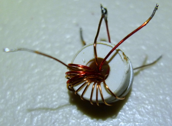
If it comes down to it, as ILYA said, this is a tiny inductor, and likely not all that difficult to hand wind. For instance, here is a small torroidal ferrite core transformer that I just removed from a bum fluorescent electronic ballast:

Two of the windings (there are three) each measure 22.1uH, in series they measure 88uH (as predicted by tight coupling). I wouldn't necessarily recommend this particular coil form for Theremin work as it could easily be very temperature sensitive (ferrite formulations usually heavily favor small size over temperature dependence). An IF transformer might be a better choice because it is normally used in resonant mode, and thus designed for that. But a ferrite torroid might be an OK place to start, and if temperature dependence is a problem, then pick something else.
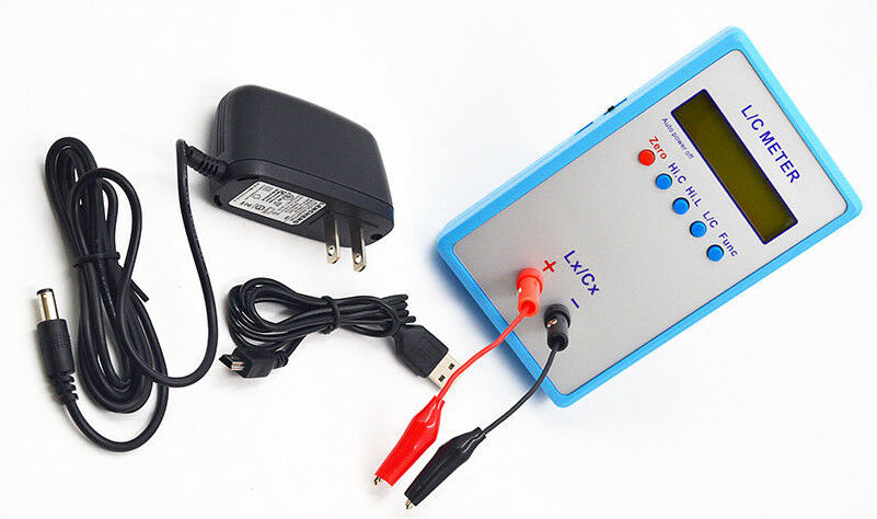
If you want a good LC meter for this kind of work, I recommend the inexpensive resonant type you can buy on eBay:

It's sensitive enough to (sort of) measure antenna intrinsic capacitance (~10pF) directly, which is kind of amazing.
I also wanted to mention something I stumbled across a while back [LINK] which I've dubbed "the invariant". All simple analog heterodyning Theremins have essentially the same response in terms of octaves per given hand movement. If you don't have the right inductor, within limits you can use any value inductor and then adjust the value of the padding capacitor across the antenna, and you will get the same heterodyned response as output. You don't tune for absolute frequency, but for heterodyned response. So: if you can get the thing to oscillate reliably, then you can likely adjust things to be indistinguishable from the original circuit.
Are you guys not using spice? LTSpice is free and works well for Theremin oscillator explorations.


