"There is no reason to implement symmetric oscillator if it gives the same drive voltage swing." - Buggins
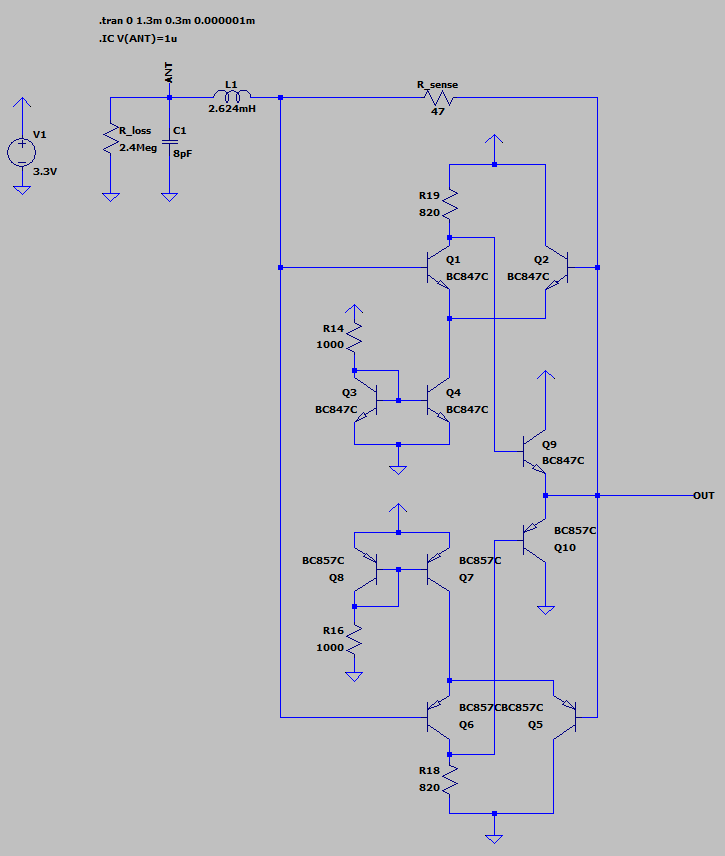
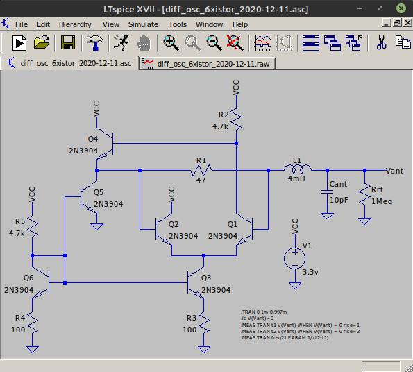
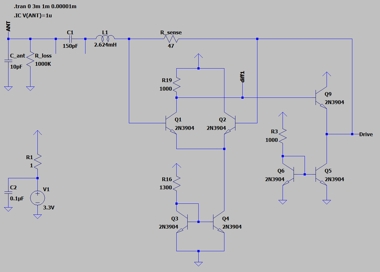
Your symmetric oscillator is quite pretty, though i haven't bench tested it at all. I messed with it in simulation this morning some more but couldn't get the drive current to behave and so gave up.
"Are you reusing half of current mirror just for economy of 1 transistor and 1 resistor?
Doesn't it make sense to increase transistors current? As I see from datasheet, hfe has maximum at 5-10mA.
R3,R4 can be removed at least if separate current mirror is used for output stage (2 resistors removed, 1 resistor + 1 transistor added)."
I'm probably missing something important, but I really like to minimize overall current draw. I'm OK with 5mA, but too much more than that and you might start running into heating drift issues. The coil itself doesn't need much at all in the way of current.
"Still hoping to get oscillation working on antenna touch. Could you please check on breadboard if adding of 150pF cap between inductor and antenna prevents oscillation from stopping on antenna touch?"
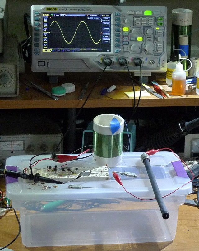
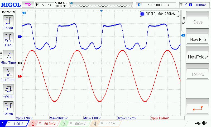
Just tried 100pF in series with the antenna, and touching it kills oscillation. It must be the resistance of my hand, because I stuck a 103 (10000pF) from antenna to ground and it oscillates at 27.5kHz with 8Vpp, which is the correct calculated frequency for a 4mH inductor.
But I can grab the insulated (heat shrink tubing) rod antenna with both hands and oscillation continues just fine, even without series C.
Even my D-Lev oscillator craps out with actual touching of the bare metal plate, I think that's just life when it comes to simple high Q oscillators. And insulation is your first line of defense against ESD. The universe wants you to insulate those antennas! ;-)
[EDIT] This is one of those rare oscillators that actually works better on the bench than in simulation, usually it's the other way around. Lots of nuance that takes both simulation and bench testing to really grasp.
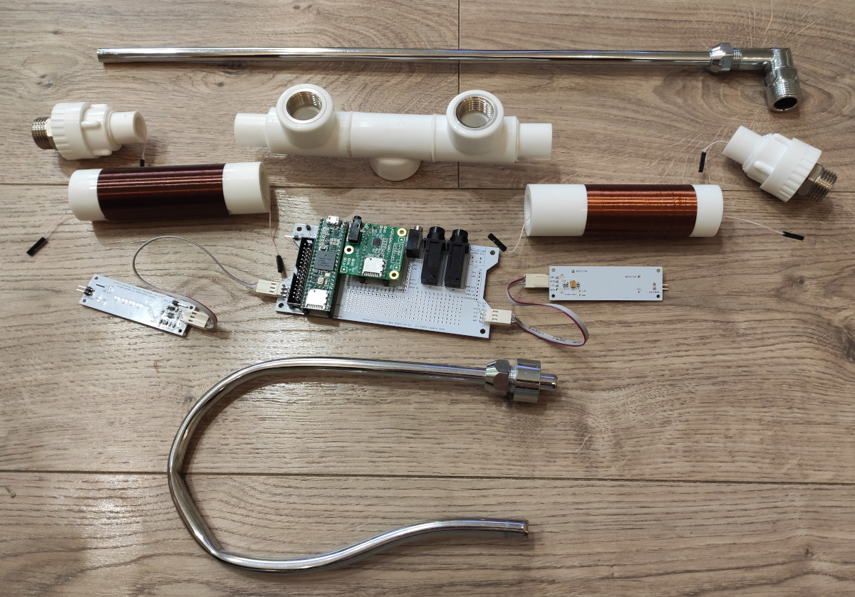
One could make a really neat digital Theremin with this oscillator as it doesn't need the C divider connection that the D-Lev requires, so the coil and antenna could exist together on the other side of a UHF connector, looking all spiffy and coilish and stuff. Might need larger L values though, like 2mH & 4mH, or 4mH & 8mH, or perhaps a bit of C padding. The UHF outer connector could be grounded without hurting anything as the connection is low-Z. No tuning of the C divider would be necessary either. ESD protection could be on either or both sides of the connector, with no real parasitic capacitance issues. Lots of possibilities.
![]()
