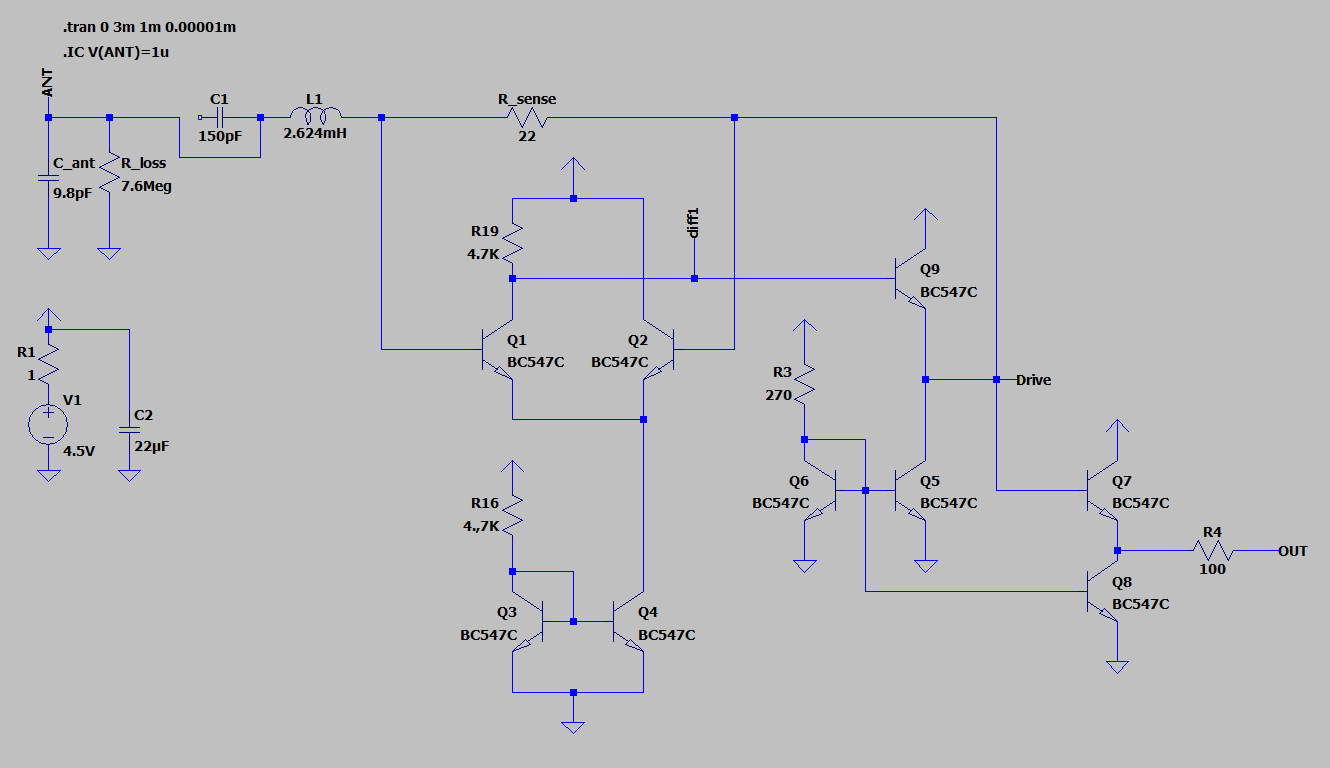
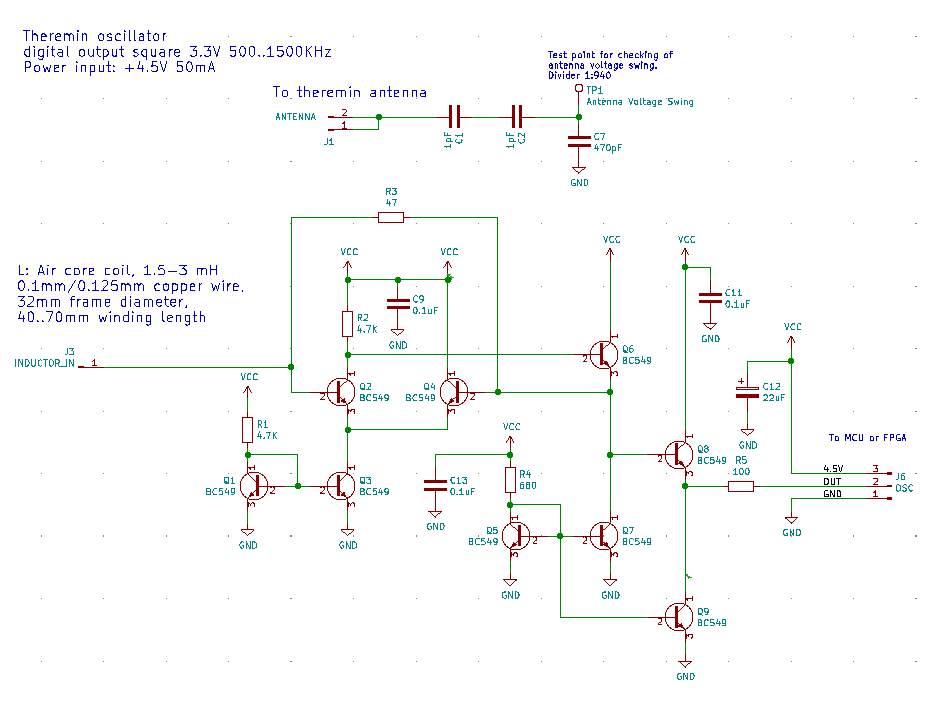
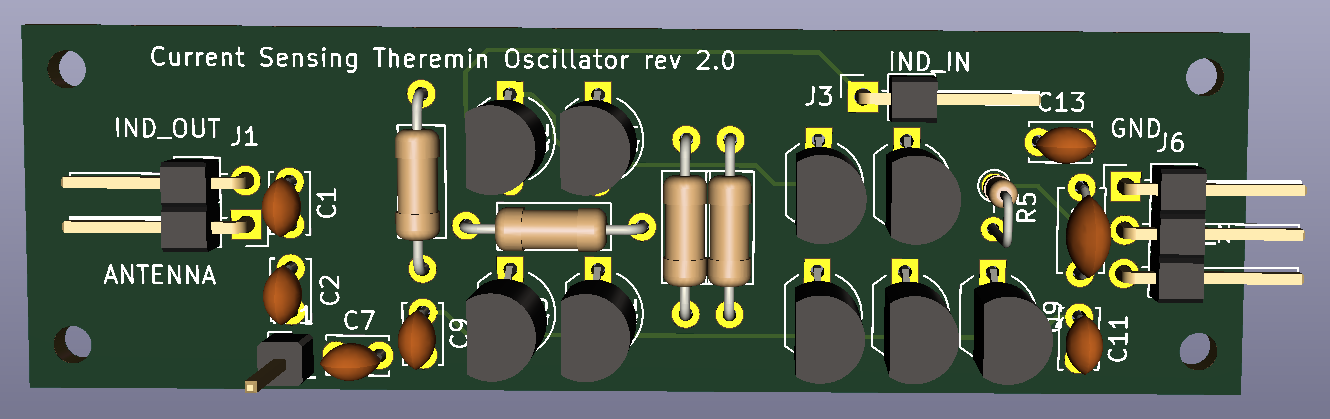
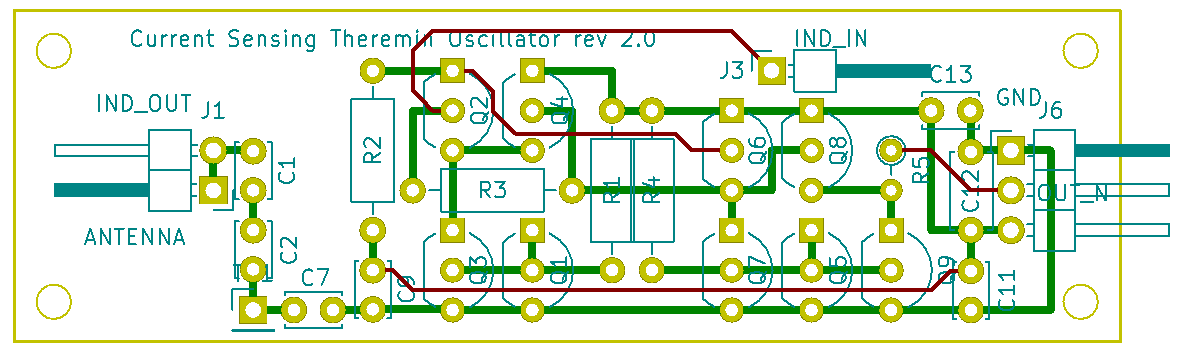
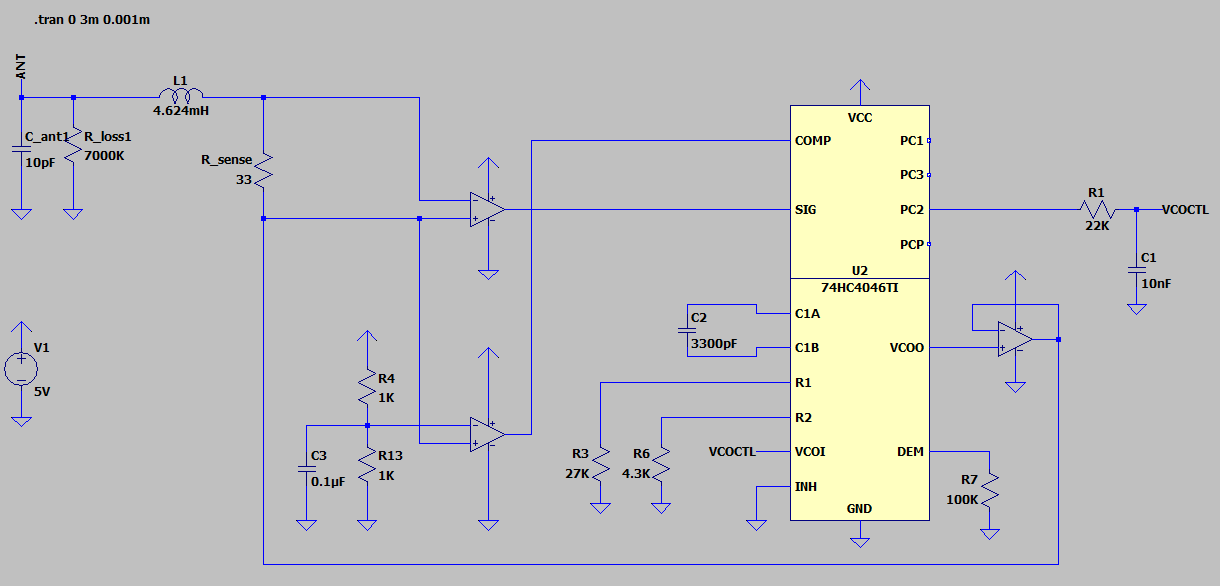
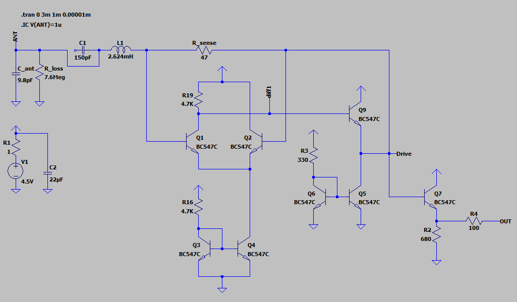
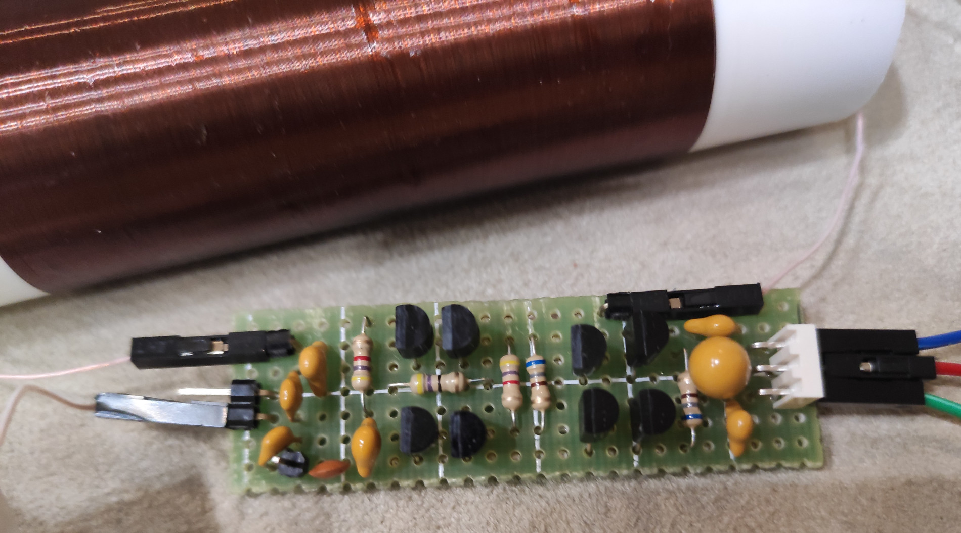
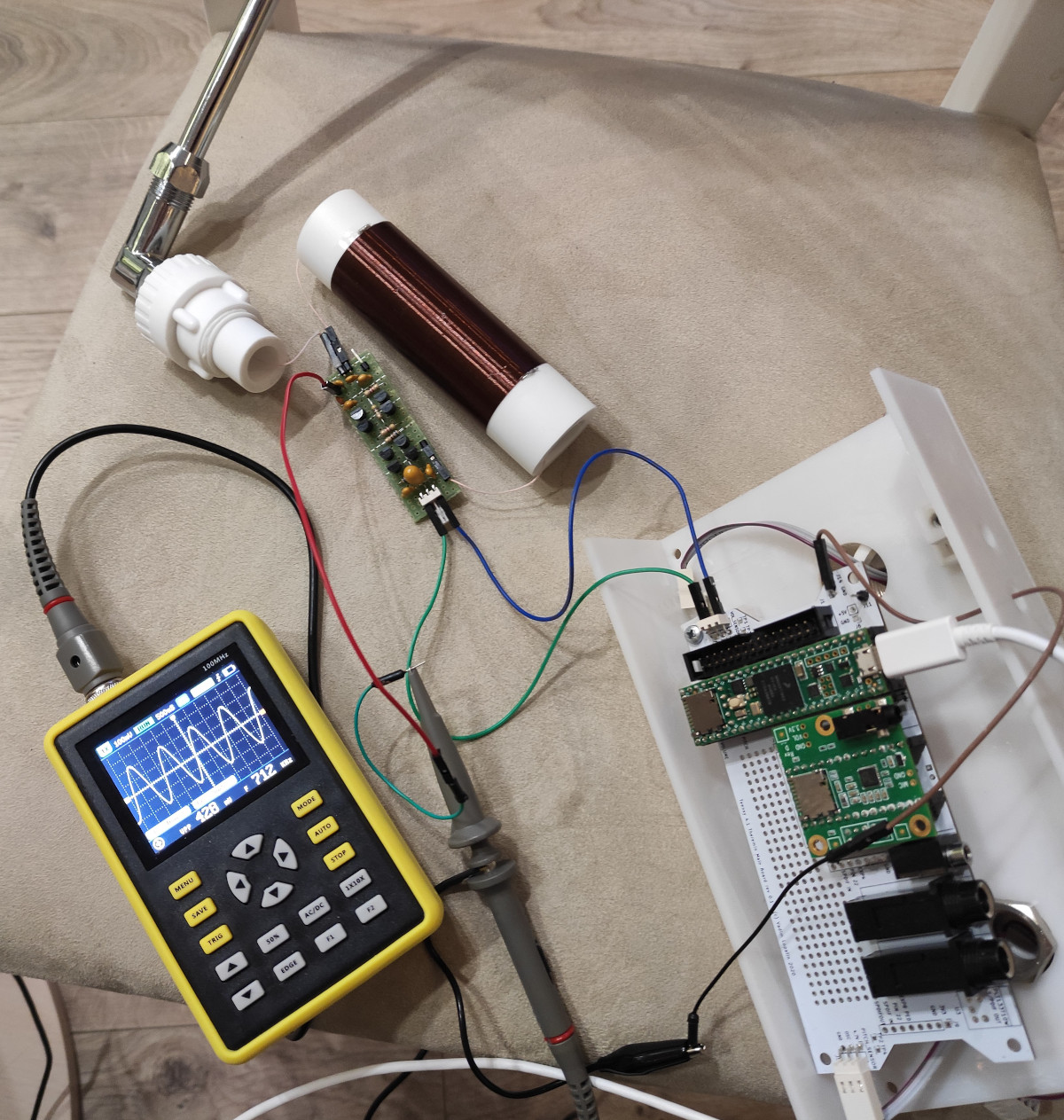
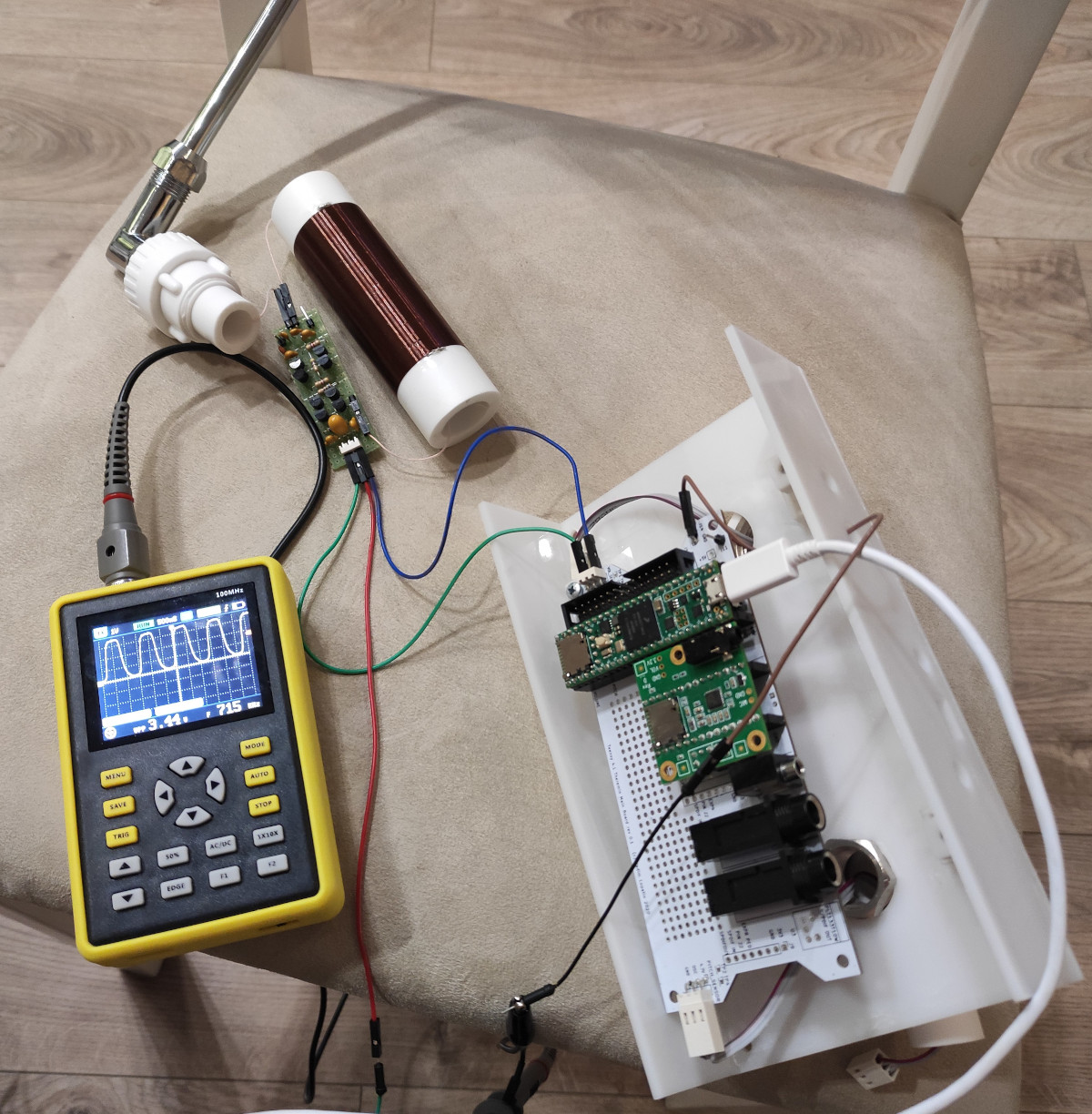
Testing of modified dewster's current sensing BJT difference amplifier (LTSpice model link) soldered on prototyping board.
It's awesome at first sight. (Measurement of stability and main hum level with MCU - TBD)
Results are better than expected according to simulation.
Tried to tune model parameters to match test results. R3 on real device is 680 Ohm. To match measured voltage swing I've set R3 to 330.
With 680 no antenna swings near 400Vpp can be reached.
Transistors used: BC549C, Hfe 630..650, pairs matched for differential cascade and current mirrors.
Output buffer: emitter follower shifts drive signal down by 0.7V to 0..3.3V range.
Powered from 4.5V (regulator on teensy theremin board).
Built in capacitive voltage divider for measuring of antenna voltage swing: 0.5pF (1+1 serial) : 470pF = x940 attenuation.
Testing with two inductors:
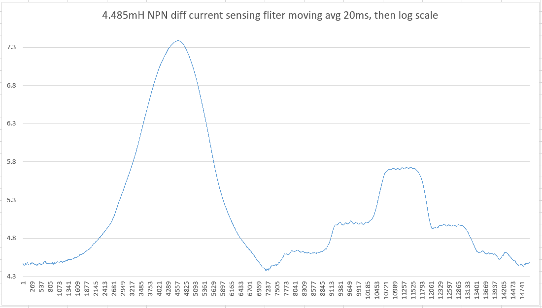
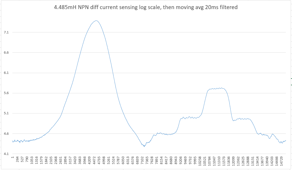
4.485mH 133.5 Ohm 0.1mm wire 77mm winding length on 32mm polypropylene frame
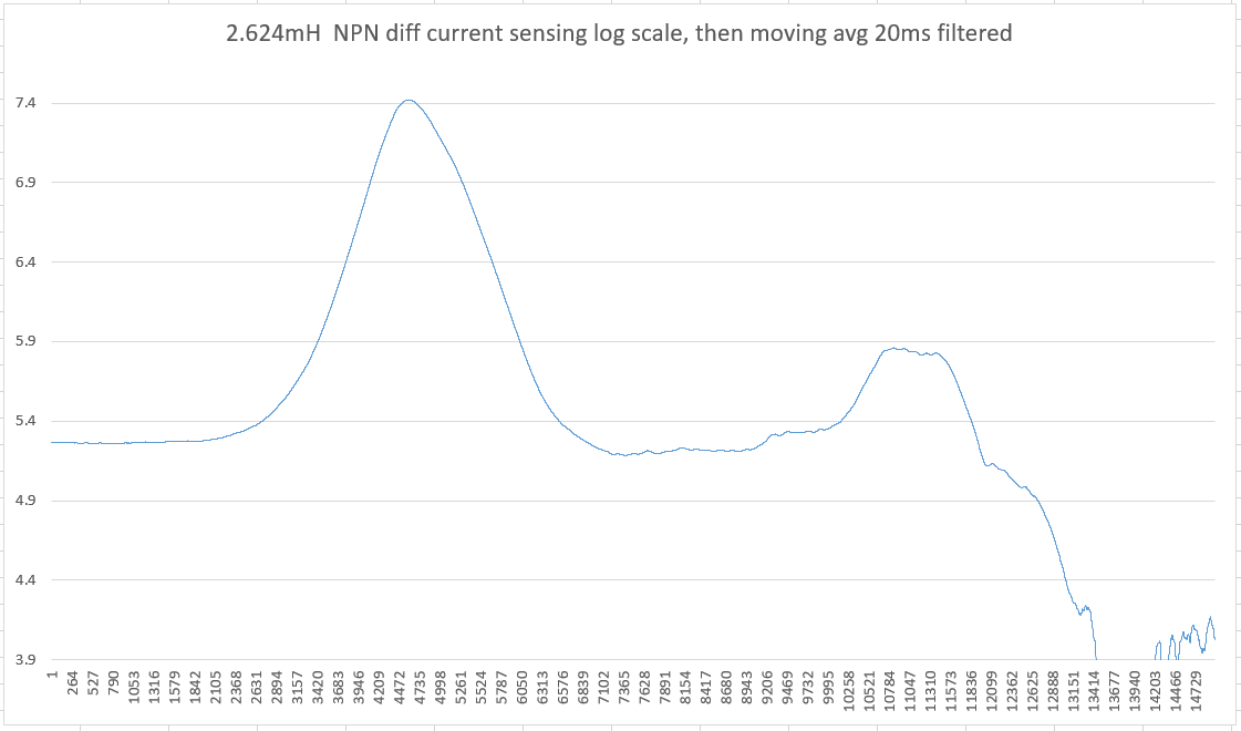
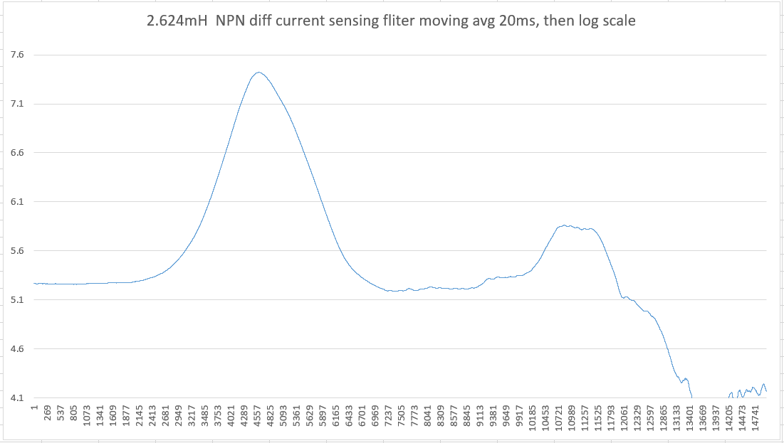
2.624mH 66 Ohm 0.125mm wire 66mm winding length on 32mm polypropylene frame
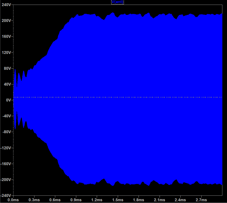
Antenna swing measured via 1:940 divider:
Output signal waveform.
Falling edge is slower because of emitter follower's 680 resistor.
Drive signal from amplifier: 3.68Vpp
Inductor input (drive after R_sense=47 Ohm): 3.36Vpp
Output signal, close to square, 0..3.45V (is it safe for 3.3V non-5V tolerant MCU input?)
Optional 100pF in series looks useless. Tried in hope that touch behavior will be better. Just lowers antenna (and hand) capacitance.
With both inductors, touch test results are similar.
Light touching of uninsulated antenna stops oscillation. But if touch surface increases (e.g. grab antenna with hand) oscillation restores - with smaller swing (30-70V) and 200-300KHz frequency.
Light touching of antenna insulated with paper doesn't stop oscillation, just antenna swing drops. But if touch surface increased, oscillation can be stopped.
After removing of hand oscillation restores instantly.
Interesting: connecting only one side of inductor, w/o antenna on another side gives good oscillation at 2MHz.
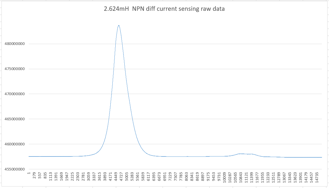
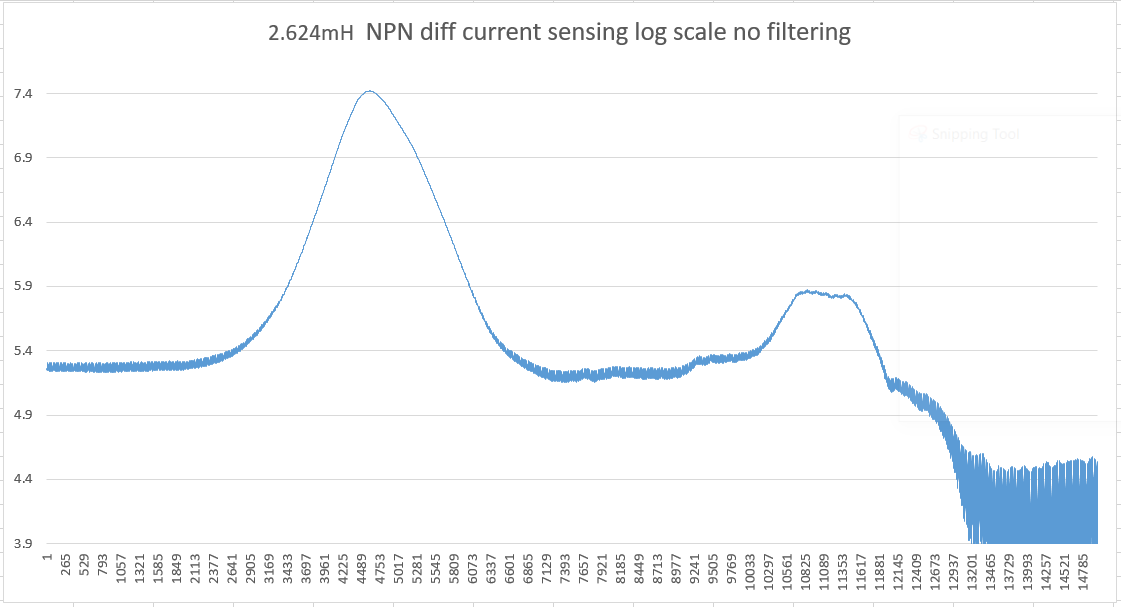
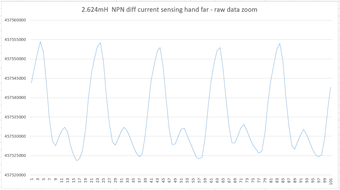
Results for 2.624mH inductor:
Hand far from antenna: 937KHz, swing 432mV from divider (397Vpp on antenna)
Hand (finger) 1 cm from antenna: 865KHz, swing 300mV from divider (282Vpp on antenna)
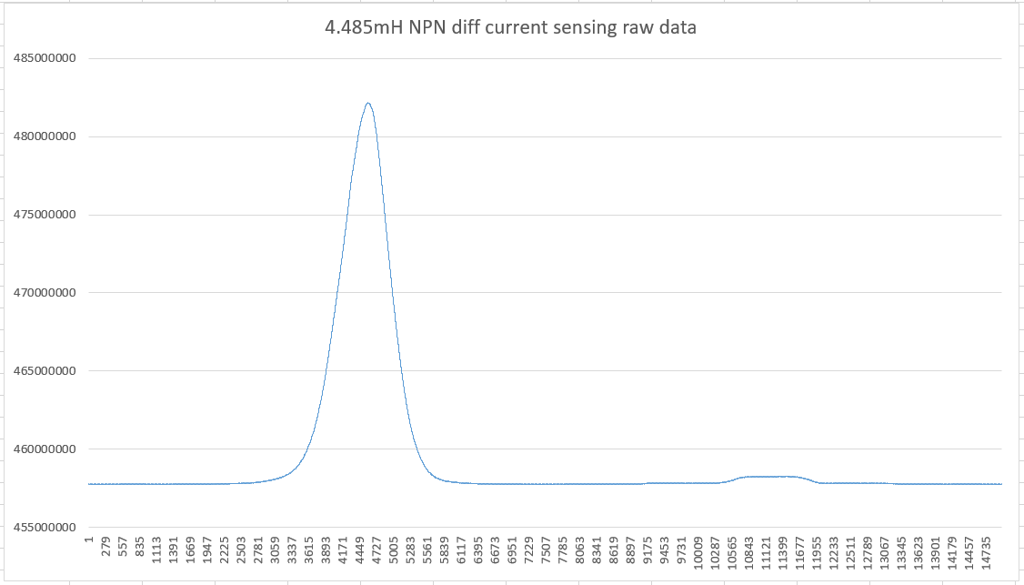
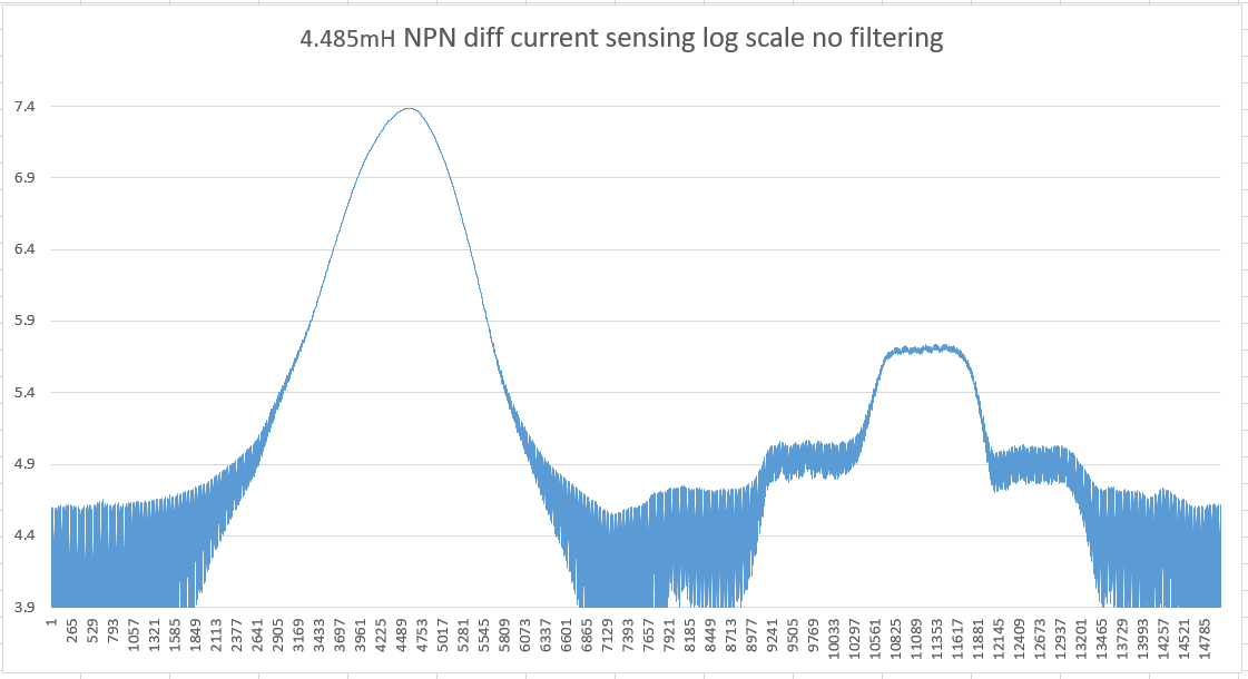
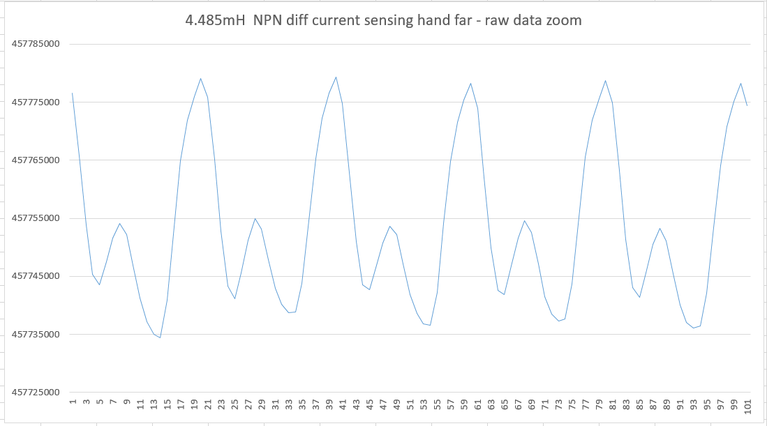
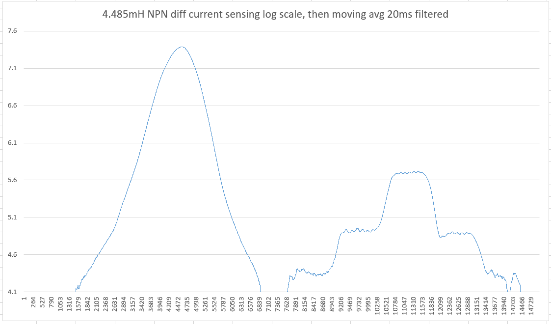
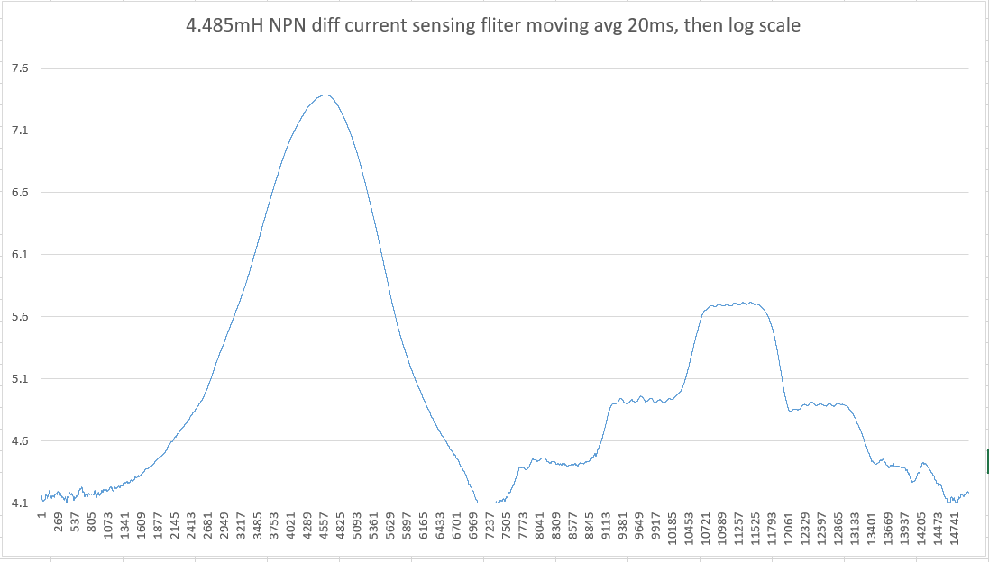
Results for 4.485mH inductor:
Hand far: 730KHz, 450mV swing (423V on antenna)
Hand (finger) 1cm from antenna: 680KHz, 250mV (235V on antenna)
With an air core I can stick a 17" (67cm) jumper wire between the drive resistor and the 6mH air core and it still looks good. Two jumpers in series and I see ringing on the leading edge of the drive signal. The RF choke is less well behaved, even just one jumper gives it trouble. I didn't attempt to control the impedance here, perhaps coax might work better or worse. So it seems to depend on the mH, SRF, and Q of the coil, and any significant distance between drive and coil might be inviting interference / harmonics (or secondary HF LC). 15-30cm is probably OK for larger L air cores, but this is something you might want to experiment with to really nail down.-- dewster
Thank you for testing.
So, at first side, placing oscillator on main board and connecting inductor and antenna using wire will probably work.
I'm going to measure main hum level with Teensy MCU as I did for other types of oscillators.
Let's see how it would affect sensor performance, and if there is a difference between simple wire and coaxial.
P.S.: Merry Christmas!!!