I'm still trying to figure out a good gear ratio for the progressive motion based on some more pink thread winding tests (although I am changing colors so that my thread theft is less noticeable). With some starter gears that I've printed I will get about 1:28.125 reduction, so with the lead screw's 18 threads per inch it would take about 506 turns to make the winding traverse an inch (and add to that the width of the reversing helix).
506 turns of a single layer coil in #36 wire would be about 2.4" long, and in #28 it would be 6.4" long. This size reduction to 1" long is possible because we are going vertical with a multi-layer wind which has advantages and disadvantages. The capacitance between adjacent turns is reduced. But if you compare the capacitance between some well-separated turns on a single layer coil (for example, turns 1 and 20) with those same turns on a progressive-universal wind, they will be closer together on the latter. So the schematic of the inductor with all the parasitics will look different between the two types, with different values of parasitics between closely and widely spaced turns.
Will something be gained? Certainly the P/U wind will give more inductance in a given volume than a single layer coil, which is the whole point. I will have some control over how much spread I can get per turn, so end-to-end capacitance can probably be managed. The self-resonant frequency is bound to drop, but within reason that should be acceptable. I'm hoping that the ability to increase wire gauge or even use some thicker Litz wire without affecting the length of the coil past the optimum aspect ratio (length/diameter) will result in smaller coils that still perform well at RF frequencies.
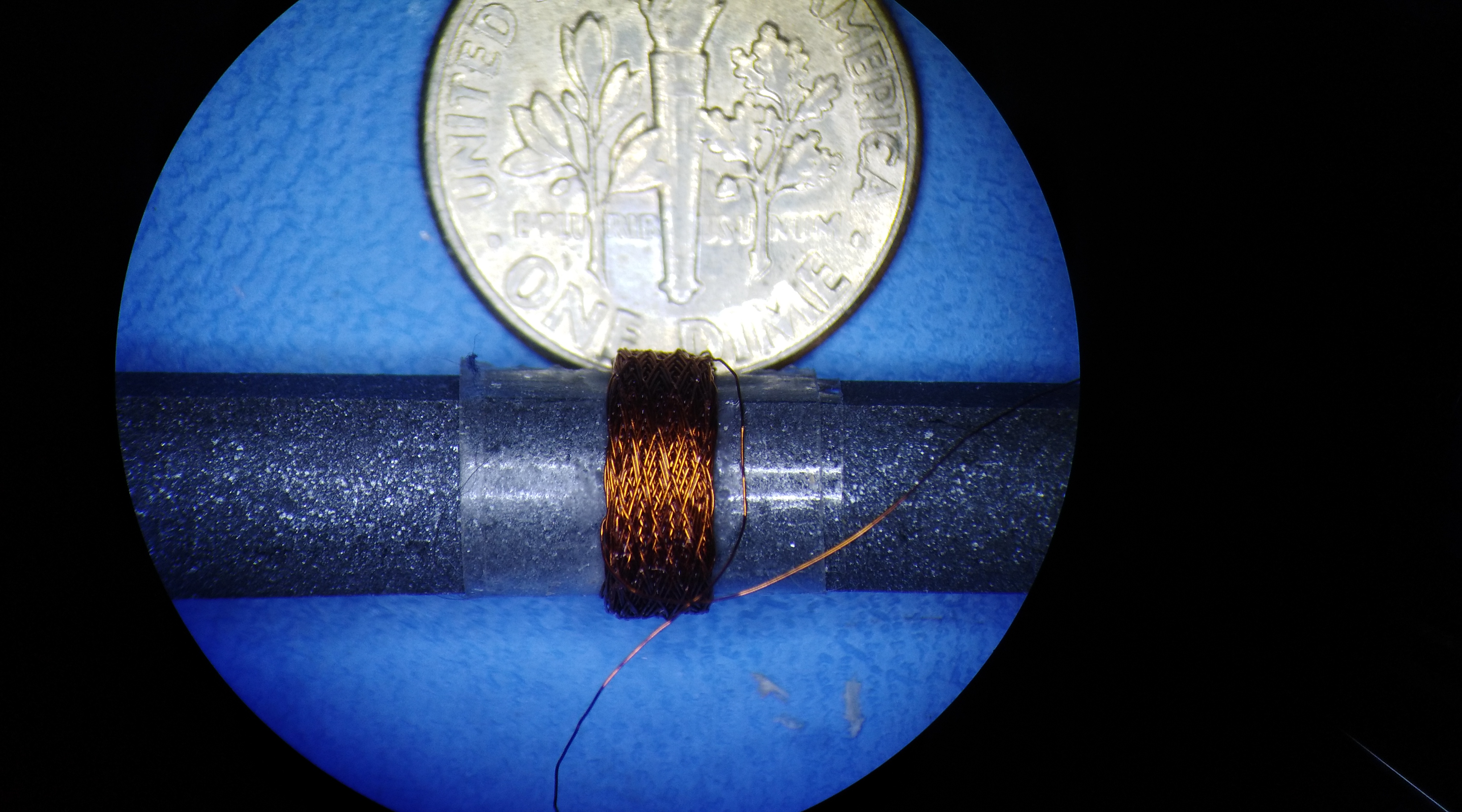
This isn't what I'm building this winder for, but here is a test of what it will do so far. This is a random number of turns (until the wire broke on me) of #42 wire on a .25" ferrite core. The honeycomb wind is holding together without binder, although I expect that I will need some to go higher in a narrow section like this. This particular coil is almost exactly 1.25 mH.
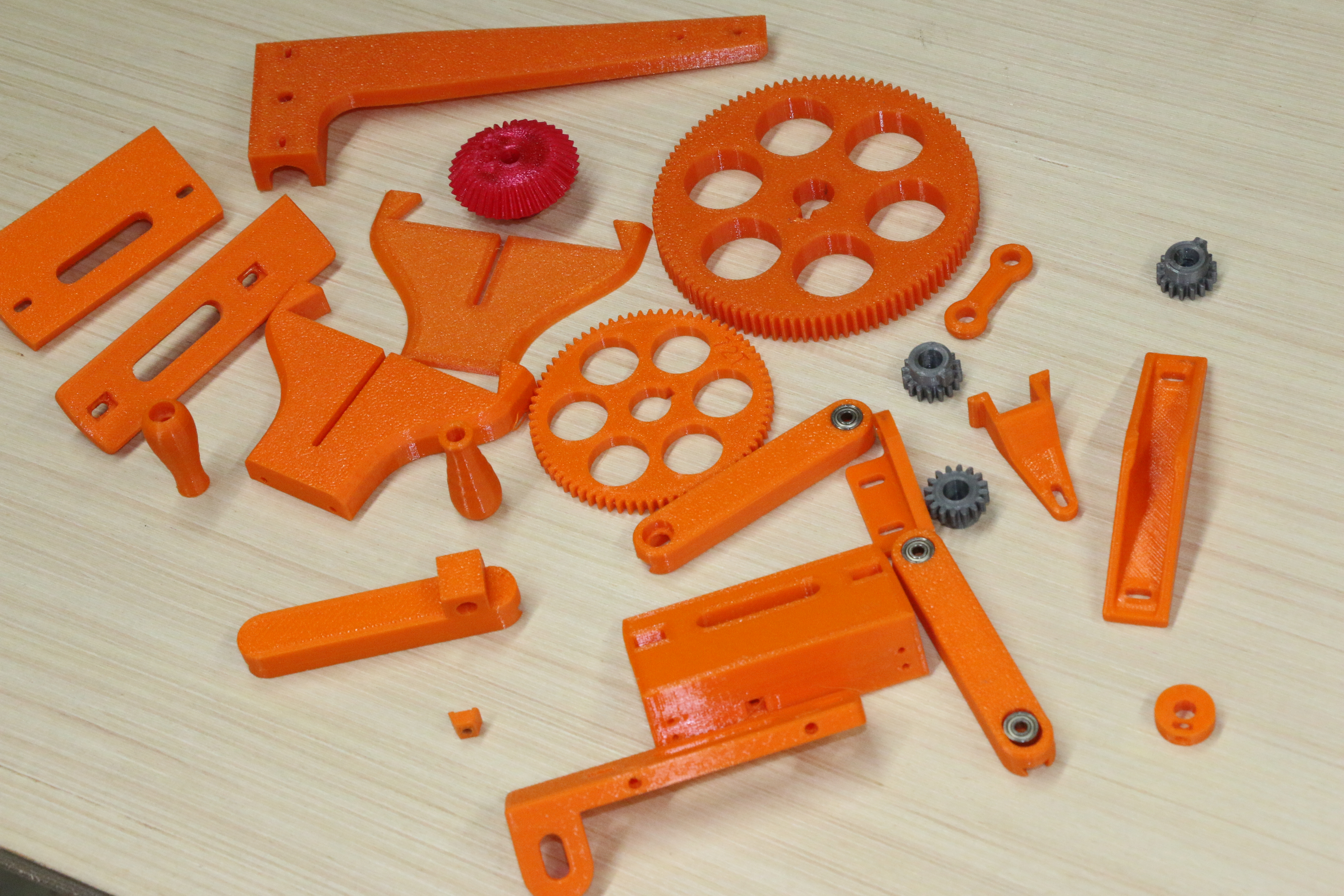
In the meantime I'm frantically designing and printing parts for the progressive gear train so that I can wrap this up and get back to other business. It should be noted that behind every successful printed part lies a bin of those that didn't make the cut. I do wish that this stuff could be easily recycled.
Some of the duds: