LC Tank / Linearizing Coil Excel Simulation

Posted: 4/14/2012 4:44:45 PM
dewster

From: Northern NJ, USA

Joined: 2/17/2012

Thanks Thierry, I'm looking at these data sheets:

Bourns (merged with Miller?) 6306 (only $1.78 @ mouser):

http://www.bourns.com/data/global/pdfs/6300_series.pdf


Hammond 1535G:

http://www.hammondmfg.com/pdf/5c0037-38.pdf


Could you point me to the Coilcraft data sheet?

Posted: 4/29/2012 3:56:03 AM
dewster

From: Northern NJ, USA

Joined: 2/17/2012

New spreadsheet v3 simulation is up:

http://www.mediafire.com/view/?lmm7dn4l34788bn

The coil core losses are now modeled via datasheet parameters.  It also now calculates coil currents, which can be surprisingly high with high voltage swings in the tank and / or at the antenna.  As before, all of the coil parasitics are calculated via the methods in this paper:

"Modeling Non-Ideal Inductors in SPICE" by Martin O’Hara Technical Manager, Newport Components, U.K. November 8 1993

There's a new worksheet at the end that estimates antenna capacitance based on antenna length and diameter, as well as rough hand capacitance calculations and linearity graph of frequency & octave vs. hand distance - both based on the methods described in this paper:

"Physics of the Theremin" by Kenneth D. Skeldon, Lindsay M. Reid, Viviene McInally, Brendan Dougan, and Craig Fulton, 1998

Posted: 4/30/2012 4:48:07 AM
dewster

From: Northern NJ, USA

Joined: 2/17/2012

"Your spreadsheet I studied and it is way over my head, I must resort back to the design method of sniffing for smoke."

Those two papers are pretty down-to-earth as these things go.  Actual equations based on actual lab results.  Theory correlating to the physical world is about as good as it gets in engineering.  Though my spreadsheet could probably be more self-explanatory. 

The spreasheet makes it pretty clear that the EWS tank has a very broad resonance area, which is swamped by the linearizing coil and antenna capacitance behavior.  The tank seems to be there mainly to stimulate the external LC, and to detect where it is resonating.  Without detailed simulation I'm not sure I would understand that.

As always, should you or any of your IM force be caught or killed, the Secretary will disavow any knowledge of your actions. Good luck, Jim. "This post will self destruct in 24 hrs."

You're getting a rich timber from that circuit RS Theremin!  You shouldn't yank so many of your posts down, I find them quite interesting.

Posted: 4/30/2012 3:05:55 PM
dewster

From: Northern NJ, USA

Joined: 2/17/2012

"This is actually done using the standard miniature 796 kHz IF Transformer. I don't know if high oscillating currents as you mention will cook it. What do you think? The values are all the real values."

Not sure.  A lot of it depends on the voltage swing across the coil. 

I do know that the spreadsheet sim shows 23 mA for the linearizing coils in my AFE.  I consider this to be rather "high current" because the saturation point for them is 40 mA, and heating could very well be an issue for long-term pitch stability. 

For the EWS the sim shows possibly (I don't know all the parasitic values for the tank inductor so this is something of a guess) around 35 mA in the linearizing coil, and perhaps 25 mA in the tank coil.  The tank coil also provides DC bias, so that would have to be added.

Posted: 12/27/2012 1:53:44 PM
dewster

From: Northern NJ, USA

Joined: 2/17/2012

Thought I'd put a link to the latest spreadsheet:

http://www.mediafire.com/?bgzc363ctdcx8rk

I was playing around in it with the EWS circuit and noticed fairly high tank current (~60mA) when the tank resonance is set a bit below that of the EQ resonance.  This is maybe too much for a 2N3904 long-term?

Posted: 2/1/2013 6:06:18 PM
dewster

From: Northern NJ, USA

Joined: 2/17/2012

Latest spreadsheet is now up:

http://www.mediafire.com/?044pc03d9c4a6jd

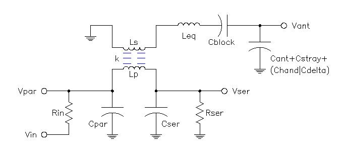
The circuit (above) can simulate single coil and transformer tanks, and parallel and series tanks including those with pre-RC phase shift (Smirnov D-sensor).  The bulk of the simulation is now coded in VB, which is reeeeally slooooow, but is much easier to read and maintain.

The coil designer worksheet is much improved as well.


- Revision History -

2013-01-31 : v6
> "Bode" VB code seems OK, checked it against an LTSpice sim.
> Transferred "Bode" VB code over to "Linearity" worksheet.
> Added handy "Reference Designs" worksheet.
> Tank inductor is now a regular transformer with Zpri & Zsec windings.
> Consolidated L parasitics calculations to one worksheet, moved explanatory text there.
> Deleted "Full Sim" worksheet, use "Linearity" instead.
> Changed "FR Sim" worksheet name to "Bode".
> New / changed calcs in "Inductor Design" worksheet, previous method gave non-convergence in many cases.
> Moved AWG data to "Inductor Design" worksheet.
> Added "Transformer Model" worksheet.
> Most graphed calculations are now in VB (which is slow as a dog but easier to read and maintain).
> Tank modes are now series | parallel with separate phase detector target (degrees).
> Unrolled phase for nicer graphs.
> Added manual "Sim!" button to "FR Sim" worksheet and reduced to 100 points due to slow VB calc speed.
> Added button that copies simulation inputs from "FR Sim" to "Linearity Sim".
> Removed DFoM, now using %F/pF.
> Added "Complex Test" worksheet (notes on using VB with complex numbers).
> Removed "Bournes 8250 Series" worksheet (they're crap).

Posted: 2/2/2013 5:41:08 AM
FredM

From: Eastleigh, Hampshire, U.K. ................................... Fred Mundell. ................................... Electronics Engineer. (Primarily Analogue) .. CV Synths 1974-1980 .. Theremin developer 2007 to present .. soon to be Developing / Trading as WaveCrafter.com . ...................................

Joined: 12/7/2007

Hi Dewster,

This is certainly the best yet - by a long way! - To be honest, the simulation is really quick IMO - (or it is compared to doing a full circuit simulation, LOL) - a few second on my dual Xeon, whereas perhaps 5 minutes to do the same running a proteus simulation.

I have only run one simulation for my current design, and the results are close enough that I believe they verify what you have done (certainly on the Bode) - I trust your linearity results - but I cannot verify them against simulation of my circuit in proteus, because I cannot directly generate a linearity plot from my simulation (this is the really useful thing about your spreadsheet).

Once again, Many thanks!

Fred.

Posted: 2/2/2013 7:43:49 PM
dewster

From: Northern NJ, USA

Joined: 2/17/2012

Glad it seems to be working for you Fred!  The VB is a lot easier to write and maintain.  It's basically still just simple series and parallel impedance combinations, with some simple voltage divider action at the end.  If anyone wants more in-depth explanation I'd be happy to supply it.

This was after a month or so of coming to intellectual grips with transformers.  I studied them some in college, the usual "enough to do the homework" but it didn't really sink in, and it was more from a power angle.  Two coupled coils are very much reflections of each other - surprisingly the "leakage" (uncoupled) and "magnetizing" (coupled) inductances of both coils have identical corresponding values when seen through the impedance transformation, so the shared flux produces essentially a single shared inductance entity between them.  Fascinating stuff!  It also took me a while to figure out real-world measurements (had to play around with a cannibalized 6310 and some hand windings) - I believe the inductance ratio is more meaningful than the turns ratio, particularly when there is no ferrous core present to concentrate the flux.

The inductor designer worksheet should be useful to those who wind their own solenoid-style air cores, which I intend to put to the test in the coming weeks.  Not sure whether PVC or phenolic tubing would be the better choice for the coil former (from coefficient of thermal expansion and relative permittivity standpoints).

Posted: 2/5/2013 7:42:22 PM
dewster

From: Northern NJ, USA

Joined: 2/17/2012

Riddle me this: After playing with my Inductor designer and the Inca program, I'm wondering why the heck the EQ coil in most tube type Theremins is so long (compared to its diameter)?  Long coils aren't well coupled to their own windings, meaning you need a lot more windings to get the same inductance value.  Is it:

1. To somehow reduce self-resonance (i.e. self capacitance) of the EQ coil? 

2. To get the top end of the EQ coil physically near the base of the pitch antenna? 

3. Theremin couldn't obtain tinier diameter wire so he had to make it longer to obtain the desired inductance value, and everyone just copied his design down to the dimensions and wire of the EQ coil? 

I don't get it (but suspect it's a combination of 2 & 3).

For my own air core designs I'm going to shoot for the squattest single layer coil I can make (within reason, coils are an amalgam of hard and soft compromises).  But I haven't actually made any yet, and feel like a bit of an idiot for not understanding the above conundrum.


Quick transformer test:  Say you have a single winding that measures 1mH.  Say you closely couple a second 1mH winding to the first.  Will the inductance of the first winding change?  (I'm pretty sure I know the answer.)

Posted: 2/5/2013 8:18:32 PM
RS Theremin

From: 60 mi. N of San Diego CA

Joined: 2/15/2005

"Quick transformer test:  Say you have a single winding that measures 1mH.  Say you closely couple a second 1mH winding to the first.  Will the inductance of the first winding change?  (I'm pretty sure I know the answer.)"

An observation I made during the start of my theremin learning curve was:

I used two 100uh ferrite core chokes in series but physically parallel to one another for a method of tuning. If they were brought closer together the inductance increased to more  than if they were totaled separated. If one of the chokes was installed in the opposite direction then inductance would decrease bringing them together.

So my answer is yes they have influence on each other, your 1 mH primary could become more or less depending the direction of the coupled turns relative to the primary.

It has been a while so I may be confused!#$%

Christopher

You must be logged in to post a reply. Please log in or register for a new account.