Let's Design and Build a (mostly) Digital Theremin!

Posted: 10/16/2018 2:10:54 PM
pitts8rh

From: Minnesota USA

Joined: 11/27/2015

I'm almost certainly overstating any issues associate with ferrite.  Certainly even crazily temperature dependent formulations, when loosely coupled / air gapped, will necessarily be incapable of causing too much trouble in any department.  I just think ferrite, like non NP0 dielectrics in capacitors, should be avoided when the avoiding is easy to do.  I certainly don't mean to play the retro card, but if big honkering coils are somewhat accepted / expected by the Theremin field at large, then why not be a bit idealistic with these components which are so central and critical to its operation?  It's one of those rare opportunities where the aesthetical desires of the electronic enthusiast public intersects directly with the practical optimization desires of the designer / engineer.  They (to me, and perhaps incorrectly) convey a certain level of mastery, gravitas, and craftsmanship that tiny pi-wound chokes just can't.

I agree that large air-core coils can be a thing of beauty for a theremin and add a retropunk look to an otherwise boring piece of electronics.  We no longer even have the silver sparkle and glow of vacuum tubes, but coils give a nice tesla-coil feel. 

But countering this argument is the fact that the inductors should ideally be lumped elements and not distributed (in the literal, not microwave design sense) and need to be located immediately at the capacitive elements, lest they become part of, and distort the fields.  For your plate design they are a perfect choice and easy to locate. For vertical coils merging into the vertical pitch rod such as the RCA, this is less noticeable than if you had, for example, the horizontal arm of the EW Pro as one long air coil.  It's not a certain problem, but something to think about and it may even be useful to intentionally do so.

My interest in considering the use of a small ferrite was solely to keep the coils the same diameter, for reasons which will soon be apparent.  Fortunately the smaller gauge wire alone did the trick.  I wanted to make sure that there was nothing super-critical in the oscillator design.  I'm not a fan of PVC, and in the future I will probably use phenolic tube, but with the choices of colored magnet wire available, these coils are pretty as well as functional.


Posted: 10/16/2018 4:11:41 PM
dewster

From: Northern NJ, USA

Joined: 2/17/2012

"But countering this argument is the fact that the inductors should ideally be lumped elements and not distributed (in the literal, not microwave design sense) and need to be located immediately at the capacitive elements, lest they become part of, and distort the fields.  For your plate design they are a perfect choice and easy to locate. For vertical coils merging into the vertical pitch rod such as the RCA, this is less noticeable than if you had, for example, the horizontal arm of the EW Pro as one long air coil.  It's not a certain problem, but something to think about and it may even be useful to intentionally do so." - pitts8rh

I agree.  Along these lines: Theremin was no slouch when it came to anything electronic, but why exactly were his pitch inductors so freaking tall?  The huge separation between drive and sense certainly minimizes self-C, but to such a diminishing returns degree it must be way past meaningless.  High aspect ratios dramatically reduce inter-winding coupling, so more wire is necessary, increasing DCR.  I can only imagine he was thinking in terms of making the coils roughly as long as the useful pitch field?  Or maybe he had very dimensionally limited coil formers / wire gauges to work with?  It's a total mystery to me.

"My interest in considering the use of a small ferrite was solely to keep the coils the same diameter, for reasons which will soon be apparent.  Fortunately the smaller gauge wire alone did the trick.  I wanted to make sure that there was nothing super-critical in the oscillator design.  I'm not a fan of PVC, and in the future I will probably use phenolic tube, but with the choices of colored magnet wire available, these coils are pretty as well as functional."

I'm using PVC because until recently I was still experimenting with former dimensions and it's easy to obtain in a wide selection of diameters, and it is structurally quite stable (in short sections).  The permittivity is around 3 which is pretty good as these things go (it only influences self-C, which itself is a vague thing conceptually).  But PVC is quite heavy in the larger diameters if you're using schedule 40 - there are thinner walled variants out there that preserve the OD dimensions, but then I suppose you might as well be ordering phenolic.  PVC cuts really nicely on my radial arm saw.

Your coils look nice!  I put the heatshrink over the whole thing and cut off the excess that ends up blocking the ID after shrinking it.  If you are mounting one end to the plate (?) you should locate the coil windings off center, more to the drive end to minimize magnetic coupling (ILYA pointed out to me that the plate looks like a  short winding). An inch or more between the nearest winding and the plate seems to be OK.  Sorry to keep repeating that, didn't want it lost in the shuffle.

Posted: 10/16/2018 5:14:18 PM
pitts8rh

From: Minnesota USA

Joined: 11/27/2015


If you are mounting one end to the plate, you should locate the coil windings off center, more to the drive end to minimize magnetic coupling (ILYA pointed out to me that the plate looks like a  short winding).

You can see that effect on the coil's swept response too.  I won't be mounting to the plates though.

Posted: 10/16/2018 5:57:24 PM
dewster

From: Northern NJ, USA

Joined: 2/17/2012

The Hardwareing: Rotary Encoders II

I sorta punted in the previous rotary encoder post.  Here's a rear view of how they connect to the FPGA pins:


Yesterday I noticed the encoder I use the most - #7, which is located at the lower right when looking at the front of the control panel, and use to select the UI page - is getting a little flaky.  I've got the software so that the UI selection hard stops between the UI page ends, so as to easily locate them with a quick spin one way or the other.  Occasionally now a quick spin CCW causes CW rotation.  So it's probably time to up the hardware debounce counter widths (currently at 8 bits).

The mechanical stuff is always the Achilles heel.  I wish I could buy guaranteed higher quality longer life encoders for $2 or even $3 each, but the market is just flooded with these cheap things.

Posted: 10/16/2018 9:53:45 PM
dewster

From: Northern NJ, USA

Joined: 2/17/2012

Digital Theremin LC Tank Q Limitations

Some basic background, experience, and conjecture on this.

R, L, C:
1. Resistors (R) convert electrical energy to heat, which leaves the circuit, never to be seen again.  (Oddly, they also spontaneously generate noise which can be quite troublesome in analog electronics - the R's in your junk box are hissing at you right now!)
2. Inductors (L, measured in Henrys) and capacitors (C, measured in Farads) are energy storage devices.  They can and do have varying types and degrees of energy eating parasitics, but ideally they act as reservoirs for energy, using a magnetic field (L) or electric field (C) as the storage medium.  Ideally all of the energy that comes in is available to go out.
3. L's are coils of wire, and wire has resistance, so the longer and thinner the wire the higher the resistance of the L - this is known as direct current resistance (DCR) and you can measure it with the ohms setting on your DMM.  DCR behaves exactly like that measured R in SERIES with a perfect L.
4. C's almost always behave more ideally than L's, that is, they are characterized less by their non-ideal parasitics and more by their energy storage capacity.  Unlike L's, C's aren't plagued by magnetic field interference, and many useful C values can be made physically quite small.  For these reasons you see lots of C's in modern circuitry and almost no L's.

LC tank, Q:
5. Functionally, L's and C's are opposites of each other.  L's are short term opens and long term shorts, C's are short term shorts and long term opens. Bizarrely, if you hook an L & C in parallel (an LC "tank") and either has any energy stored, that energy will transfer back and forth between the two - sinewave oscillating / ringing ideally forever, only decaying due to parasitic and other energy losses. 
6. This decaying is known as damping, the value of which is the fraction of total energy lost per cycle.  Q, or quality factor, is the inverse of damping.  So infinite Q = zero damping = no losses = ringing forever.
7. The resonant frequency of the sinewave oscillation of a ringing LC tank is given by 1 / [2*pi*sqrt(L*C)].
8. Just like pushing a child on a swing, small electrical pushes applied to high Q LC at the resonance frequency can result in quite large voltage oscillations across the L & C. The final amplitude is limited only by the energy losses!
9. Q directly multiplies the tank drive amplitude.  Give an LC tank with Q=100 a drive of 1V and it will swing 100V.  This is great for drowning out environmental interferers and intrinsic oscillator noise.
10. Q is measure of discrimination, so you want high Q to better pinpoint resonance frequency and swamp (by effectively putting a big flywheel on) interference.  In some instances you may want to lower Q in order to smear out resonance and operate over a larger range off of the resonance point (this is how the volume side on the Etherwave and others works).
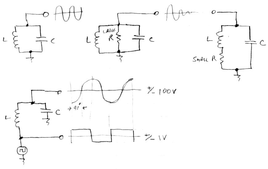
11. Adding some R to the LC tank lowers Q / smears out the resonance.  Either a large R in parallel with the LC, or a small R in series with the series L drive (see #13).
12. L DCR acts like a resistor in series with the series L drive!

LC oscillator drive:
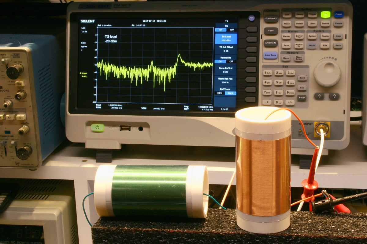
13. The most direct way to drive an LC tank with low voltage modern digital logic is to break one LC connection and insert a grounded low impedance drive.  This grounds the C and wiggles the L.  When the drive signal is at LC resonance, the unbroken LC node will swing with a large amplitude sine wave, even if the drive is a square wave, because the LC is acting like a second order lowpass filter, hugely suppressing all harmonics of the drive waveform.  At resonance the high voltage swing node will lag the drive signal by exactly 90 degrees ("quadrature").  For example, the prototype uses a ~2V p-p tank drive, and the ~100 Q tank air core solenoid L and plate antenna C cause the antenna to swing ~200V p-p.
14. An LC tank can be driven somewhat off of its natural resonance frequency and still give largish, though reduced, amplitude swings.
15. Higher Q means less room for error with phase of the drive signal.
16. It may not be obvious at first glance, but simple analog LC oscillators often depend on phase error in order to work, and may introduce losses in order to sense / time the tank drive.
17. Phase drive error leads directly to off resonance frequency error, and thus LC tank voltage swing reduction. If you're simulating an LC oscillator with perfect LC and the tank swing isn't huge, there is too much drive phase error (you're off resonance) and/or there are circuit elements wasting energy.
18. Phase locked loop (PLL) LC stimulation techniques can enforce exact quadrature between series L drive and antenna C, therefore maintaining oscillation at the exact LC resonance point, therefore maximizing tank / antenna voltage swing.
19. Phase gain is Q/pi, and this is important because it is part of the PLL loop gain, so it must be accounted for (loop gain < 1 for stability, loop gain determines loop bandwidth).  You can directly see high phase gain on a scope by observing both the drive and antenna signals with variable frequency drive - the relative phase of a high Q tank will suddenly "pop" from 0 degrees to 180 degrees when transitioning through the resonance point unless you're adjusting the drive frequency quite slowly.  At quadrature the "pop" rate is at its peak.

Theremin losses:
20. The "antenna" of a Theremin functions mostly like one "plate" of a capacitor, with the air around it the dielectric field, and anything conductive past that the other "plate" of the capacitor.
21. Human body interaction with a Theremin antenna is very much like a variable capacitor, with the human side "plate" grounded through a series R.  The closer the human hand or other body part to the antenna, the higher the mutual C, but the losses increase as well due to the body R.  You can readily demonstrate this by placing a scope probe near the Theremin antenna and watching the amplitude on the screen become dramatically reduced as the hand approaches.
22. The "skin effect" starts kicking in at fairly low frequencies, magnifying DCR.  The moving charges in the L wire flee from the center of the wire and crowd to the outer edges or skin, causing an effective reduction in the cross sectional area of the wire, raising the AC resistance, and lowering Q.  (My solenoid spreadsheet calculator takes this into account.)
23. There are RF losses as well, and I believe it is these that ultimately place an upper limit on LC tank Q.

When I first started winding coils I reasoned that the L DCR would be the overwhelming LC tank Q determinant, so I tended towards larger diameter wire which required physically large coils.  But the huge Q's never materialized, and coils wound with thinner wire behaved about the same.  It's obvious that a Theremin "antenna" actually behaves like a very short, highly resonant, coil loaded dipole with capacitive cap.  And I believe the way those work is to jack up the antenna voltage swing via LC resonance, and thus somewhat make up for their huge impedance mismatch to the "ether" via sheer amplitude.  Sort of like screaming to be heard because someone has their hand clamped over your mouth.

Anyway, it doesn't take much in the way of drive phase error or R or RF losses to seriously lower a high Q swing, it's a fairly tenuous thing.  The most you can hope for here is maybe 200 or so, and that's really pushing it.  Lucky for us, 100 or even less seems to work fine, though I worry about the RF disturbing transmissions and such.  

[EDIT] The shorter the antenna the less well it behaves as an antenna, so the lower the RF transmission.  So a circular antenna fed from the middle is something of a best-case here in terms of highest C interaction with the hand and smallest physical dimension to radiate RF?  I'm strongly thinking that my next build will have circular center-fed antenna plates, perhaps with some kind of bulls-eye painted on or a contrasting outer rim, to see them better peripherally.

Posted: 10/19/2018 6:29:22 PM
dewster

From: Northern NJ, USA

Joined: 2/17/2012

Jurgen Haible String Filter

Before my (serious Theremin & synth work) time, but this fellow seems to have done a lot of analog synth design.  He tragically passed in 2011 (though I'm not sure how).  Long ago (2004?) I downloaded an MP3 of his cello string filter and was blown away by it (at the time).  You can read about the filter here [LINK] and an audio sample is here [MP3] (which is archived via the Wayback Machine).

The filter is interesting because it's 40 resonators (band pass filters) spaced exponentially, and then shaped via a few more broader filters plus a notch.  To my now more discerning ears it sounds pretty much like a sawtooth through a complex filter rather than a cello, though it's definitely amazing to hear the transformation the filter makes.  My current cello filter of 6 resonators plus highpass non-harmonic resonator has no global shaping and I think it sounds quite a bit better than his analog filter, though that could have a lot to do with the choice of stimulation waveform too.  I've seen resonance plots of the violin and, except for a slight upward tilt to the whole thing, they look like a straight resonance bank without any other shaping.  So I'm not convinced shaping is necessary or even desirable.

So much of synthesis is dynamics, and I think the Theremin lends much realism to cello synthesis via the smoothly interactive pitch and volume.  It's glaringly obvious that the limited expressiveness of a keyboard isn't a good match as an input controller for this voice.

Posted: 10/19/2018 8:11:45 PM
pitts8rh

From: Minnesota USA

Joined: 11/27/2015

The string filter alone driven by a sawtooth waveform doesn't sound that much like a cello, particularly when the source is a keyboard.  But it is nevertheless impressive, I think.   The string filter was intended to be chained with a cello or violin filter which would shape the overall response of the 40-filter bank.  I think Haible built a prototype that had these additional filters, but decided not to commit these to boards as he originally intended because the most users would already have the LPF, HPF, and parametric filters needed to accomplish the task.

I ordered the boards for the string filter itself last week with the intent of trying it (if I ever get there) on one of my experimental Etherwave mods that has a sawtooth output.  The later versions of the Haible board have the provision to bring all 40 filter gains to pots.  With linear pots you can just shape the overall response much as you would with a graphic EQ.  It's a wiring mess though.

I'm on a cello-quest.  Analog or digital, whatever works.

Posted: 10/20/2018 3:56:42 AM
dewster

From: Northern NJ, USA

Joined: 2/17/2012

"The string filter alone driven by a sawtooth waveform doesn't sound that much like a cello, particularly when the source is a keyboard.  But it is nevertheless impressive, I think.  The string filter was intended to be chained with a cello or violin filter which would shape the overall response of the 40-filter bank.  I think Haible built a prototype that had these additional filters, but decided not to commit these to boards as he originally intended because the most users would already have the LPF, HPF, and parametric filters needed to accomplish the task."  - pitts8rh

Hope you don't think I'm trolling you! :-)  You brought up the filter which helped me remember that I'd encountered that page long ago and had been meaning to do a post on it for a while now, so thanks!

There are live links on his page to samples that seem to include the cello filter? 

Hailble is going at things a bit differently than me, he gets all the resonances lined up exponentially, whereas only my first 6 are more or less, with the remaining spaced linearly but jumbled, and starting low but the lowest high-pass filtered.  Mine use actual delay to generate those upper ones which might add to the hollowness, not sure about that though as a couple of resonant filters often fool my ears into thinking I'm hearing acoustic space.  Mine is more based on a physical modeling paper, but only very roughly so.

If I were building an analog string filter I'd probably take the same approach, 6 or so lower formants I could position frequency-wise and a bunch of higher ones that are static, maybe with a 2nd or 4th order HPF partitioning them.  That way you could set it to be a cello, viola, violin, etc.  I think the upper ones just have to give you some brightness and the impression that something complicated is going on up there, and the lower ones define the instrument.  Getting the Q right is a lot of it, and I believe that can be a global thing.

Haible is relying on a book that I have a copy of (PDF) for the cello resonances.  I've looked through it, perhaps not thoroughly enough (?), but have been unable to locate in it the data he is using for his filters.

"I'm on a cello-quest.  Analog or digital, whatever works."

Both approaches have their issues, but I don't think I've got it in me anymore to attempt something like an analog string filter, particularly with not being 100% certain it will turn out to be exactly what I need/want for the rest of my life.  If nothing else I imagine you'll find playing with code and settings somewhat easier than slaving over a hot iron.  Anyway, please don't get your hopes too high!  All voices get repetitious after a while, and some lend themselves to certain tunes better than others.

You seem to be approaching the antennas from a different angle, have you seen the pix of livio's Theremino?  [LINK]  I look at that and sort of wonder why I'm bothering doing what I'm doing.  NIH I suppose, and the pedagogical aspects.

Posted: 10/20/2018 9:03:42 AM
pitts8rh

From: Minnesota USA

Joined: 11/27/2015


"Hope you don't think I'm trolling you! :-)  You brought up the filter which helped me remember that I'd encountered that page long ago and had been meaning to do a post on it for a while now, so thanks!

There are live links on his page to samples that seem to include the cello filter?" -Dewster

No, but I am trolling you!

Actually there are some links that demonstrate the string filter with the either the cello or violin filter added, but I can't point directly to them at the moment.  There are several pages dedicated to Haible, some of which have multiple broken links, but it may be one of these:

http://jhaible.com/legacy/string_filter/jh_string_filter.html
http://electro-music.com/forum/topic-20360-50.html
http://sonicsheep.com/Synthesisers/4-JHStringFilter.html
http://www.tellun.com/motm/mods/jhstring/jhstring.html

The enhancement wasn't dramatic, but overall I think that when sourced using a sawtooth theremin this combination could sound very nice.


"Both approaches have their issues, but I don't think I've got it in me anymore to attempt something like an analog string filter, particularly with not being 100% certain it will turn out to be exactly what I need/want for the rest of my life.  If nothing else I imagine you'll find playing with code and settings somewhat easier than slaving over a hot iron.  Anyway, please don't get your hopes too high!  All voices get repetitious after a while, and some lend themselves to certain tunes better than others." -Dewster

I'd have to be lucky indeed to even be playing theremin in ten years, so I'm going with what I can get in hand now, and my hopes only get too high if I'm waiting for that next best thing just around the corner. I do wish I could trade some of my fruitless guitar years for more theremin practice, but I'm having fun with it now nevertheless.  I prefer string and vocal sounds because they work well with the pitch transitions of the theremin.  I would love to be able to play Clair de lune as well as Randy George, but those types of theremin voices seem difficult to me.  


As long as the Haible board set is available, stuffing it is a non-issue; the packaging (especially with 40 sliders) is the more daunting task.  I wouldn't bother designing one these days, though.  I do have high hopes for the Dewster approach as well, and we'll find out about that soon enough.

I had to laugh at this quote from the link you gave above:

"This is not a "concept". Lello built (3D-printed) several of these Theremins (each one with a new and better shape) and they are used every day by musicians, in piano bars and on cruise ships." - Livio

Now that is the user base that every theremin manufacturer should hope to corner.

Posted: 10/20/2018 7:36:29 PM
dewster

From: Northern NJ, USA

Joined: 2/17/2012

Roger, thanks for those links!  Regarding this one:

http://www.tellun.com/motm/mods/jhstring/jhstring.html

I'm listening to the pink noise samples there and they are quite impressive.  I'm often surprised at how complex sounding noise can be when filtered.  If I'm hearing it right the lower resonances sound like bells and the higher ones have much shorter decay time, which is consistent with constant Q.

For vocals and strings the levels and Q's are often all the same (except for the tenor voice), so IMO the trouble he goes to though to have level controls and patch points for each filter is way, way overkill.  If one doesn't want to stimulate certain sections then maybe just 4th order pre-filter the input signal.  And I'm probably creatively impaired here, but I can't imagine what use all those patch points might have.  It looks like an awful lot of work for dubiously enhanced functionality and exponentially more points of failure / noise / oscillation.

http://electro-music.com/forum/topic-20360.html&postorder=asc

By all accounts Jürgen Haible was quite devoted to electronic music and loved to share his experience with others.  It's generally a ton of work with little to no chance of making any money, so it makes for a bear of a side job, particularly if one has a spouse & kids.  Stealing an hour or so here and there won't cut it, stealing more than than means abdicating other significant portions of one's life. And it seems he volunteered quite a bit. Divorce and premature death seem to be something of a mummy's curse when it comes to this field.  

"I would love to be able to play Clair de lune as well as Randy George..."  - Roger

Wouldn't we all!

You must be logged in to post a reply. Please log in or register for a new account.