Antenna Geometries
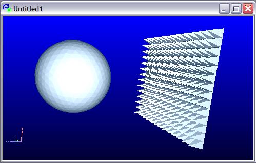
I wrote two geometry generators for FastCap: one that makes meshed rectangles, and another that makes meshed ellipses. They draw "rings" of plates (rectangles and triangles, respectively) around a central plate (a rectangle and a hexagon, respectively) with the number of rings and other pertinent values specified via command line parameters. Ring sizing is geometric, so you can make the gradient from the inner plates to the edge plates progressively smaller or larger (you generally want smaller spacing where the field gradient is largest, which gives better accuracy for fewer plates).
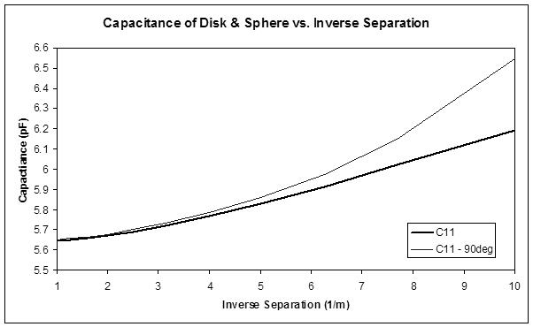
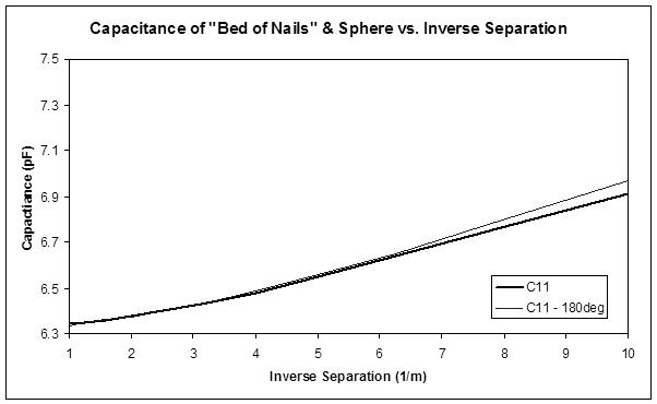
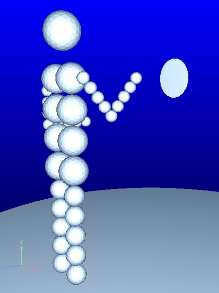
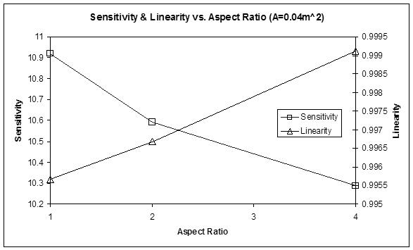
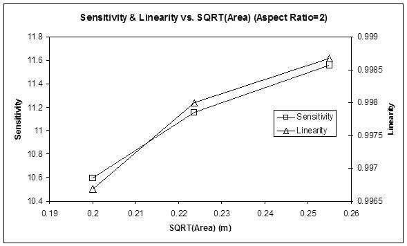
I did some FastCap runs using a hand sphere of 80mm diameter, and antenna plates with different 5 different geometries but with identical areas of 0.02m^2. The sphere was generated with a "refinement" of 3, which gives ~1.3k triangles. The plates are constructed of ~2k elements. Some results:
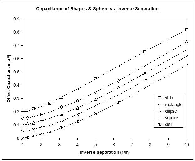
The above capacitances are artificially offset from each other by 0.05pF to avoid a plotting jumble.
In terms of linearity and sensitivity, there isn't much difference to speak of between the disk, square, ellipse (2:1 aspect ratio), and rectangular (2:1 aspect ratio) plate antennas. All have around 9.3% capacitance delta over the 0.1m to 1.0m distance, with 0.985 linearity (measured via the Excel "RSQ" function).
The strip antenna (8:1 aspect ratio rectangle) has somewhat lower sensitivity 8.25% capacitance delta, but almost perfect 0.996 linearity.
The arm isn't being modeled here, but it's pretty clear that antenna geometry isn't a major factor where linearity is concerned, at least for the case where one is using a plate antenna and working backwards through the LC and 1/d formulas.
My FastCap stuff & Excel spreadsheet: http://www.mediafire.com/download/kayzialofgadmj4/theremin_fastcap_2015-12-21.zip


