Let's Design and Build a (mostly) Digital Theremin!

Posted: 12/21/2015 8:42:34 PM
dewster

From: Northern NJ, USA

Joined: 2/17/2012

Antenna Geometries

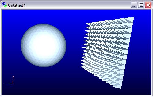
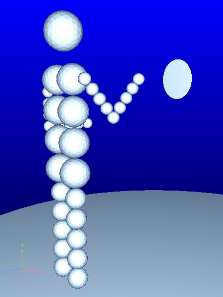
I wrote two geometry generators for FastCap: one that makes meshed rectangles, and another that makes meshed ellipses.  They draw "rings" of plates (rectangles and triangles, respectively) around a central plate (a rectangle and a hexagon, respectively) with the number of rings and other pertinent values specified via command line parameters.  Ring sizing is geometric, so you can make the gradient from the inner plates to the edge plates progressively smaller or larger (you generally want smaller spacing where the field gradient is largest, which gives better accuracy for fewer plates).

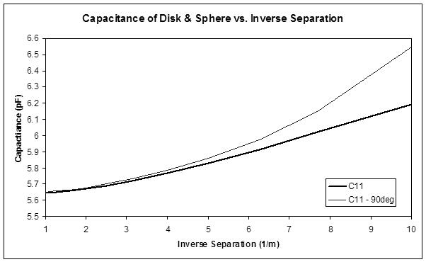
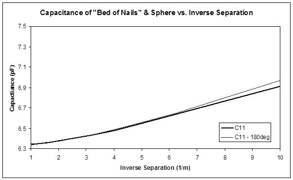
I did some FastCap runs using a hand sphere of 80mm diameter, and antenna plates with different 5 different geometries but with identical areas of 0.02m^2.  The sphere was generated with a "refinement" of 3, which gives ~1.3k triangles.  The plates are constructed of ~2k elements.  Some results:

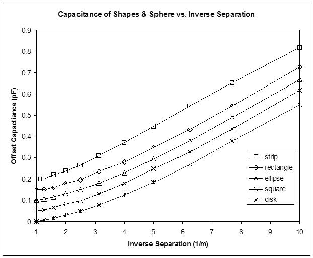
The above capacitances are artificially offset from each other by 0.05pF to avoid a plotting jumble.  

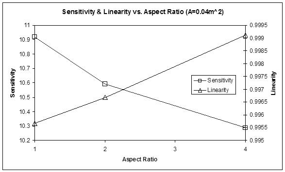
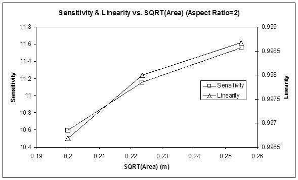
In terms of linearity and sensitivity, there isn't much difference to speak of between the disk, square, ellipse (2:1 aspect ratio), and rectangular (2:1 aspect ratio) plate antennas.  All have around 9.3% capacitance delta over the 0.1m to 1.0m distance, with 0.985 linearity (measured via the Excel "RSQ" function).

The strip antenna (8:1 aspect ratio rectangle) has somewhat lower sensitivity 8.25% capacitance delta, but almost perfect 0.996 linearity.

The arm isn't being modeled here, but it's pretty clear that antenna geometry isn't a major factor where linearity is concerned, at least for the case where one is using a plate antenna and working backwards through the LC and 1/d formulas.

My FastCap stuff & Excel spreadsheet: http://www.mediafire.com/download/kayzialofgadmj4/theremin_fastcap_2015-12-21.zip

Posted: 12/22/2015 3:19:15 AM
dewster

From: Northern NJ, USA

Joined: 2/17/2012

Off Axis Response

I performed the same capacitance analysis but with the hand sphere off axis to the plate antennas, here is a sampling of the disk shaped antenna response:

Since the x axis is inverse separation, larger numbers on it are actually closer to the antenna (closer is on the right, farther on the left).  The higher sensitivity closer is due to the sphere being physically closer to the edge of the antenna, so it isn't a surprise.  What is a big surprise is the pretty much identical response in the far field on and off axis.  I thought a plate would be at least somewhat directional in the far field but it seems this isn't the case.

Plates are more sensitive so I'll still be using them, but this lack of any directionality is a bit of a let-down.  Ah well, the truth wherever it leads.

Posted: 12/22/2015 3:42:32 PM
dewster

From: Northern NJ, USA

Joined: 2/17/2012

Just looking over the spreadsheet to see if there is anything further to glean from the results.  Here's the disk and sphere results in tabular form:

distance (m) C11 C12 Cinf
0.1 6.1926 -1.604 4.5886
0.13 6.0201 -1.3203 4.6998
0.16 5.912 -1.1211 4.7909
0.2 5.8288 -0.93407 4.89473
0.25 5.769 -0.77392 4.99508
0.32 5.7219 -0.62316 5.09874
0.4 5.6913 -0.50953 5.18177
0.5 5.6732 -0.41572 5.25748
0.63 5.6596 -0.33554 5.32406
0.8 5.6501 -0.26759 5.38251
1 5.6435 -0.21583 5.42767

C11 is the total capacitance as seen by the antenna, and therefore the LC tank.  C12 is the mutual capacitance between the antenna and the hand (ignore the minus sign).  Cinf is the absolute difference between C11 and C12, which gives us the intrinsic capacitance of the antenna, or the capacity between the antenna and the universe.  

What's interesting is that Cinf reduces as the hand approaches the antenna, something I didn't expect, though it makes sense as field lines that were going out to space terminate instead on the hand (I suppose I've always thought of Cinf as a constant).

Absolute sensitivity is the ratiometric change in C11, so the intrinsic capacitance sets something of a baseline for it.  Notice that intrinsic C changes in the opposite direction of mutual C, and that this lowers overall sensitivity.  If Cinf were indeed constant the above simulation would have ~1.4pF total C change, rather than the ~0.55pF total C change, a more than 2.5 time increase.  It seems that sharper antenna shapes (things with corners) have slightly higher total sensitivity than smoother shapes.  Sharper shapes have higher mutual capacitance change, but this is offset by a higher intrinsic capacitance, so it's something of a wash.

If you look at the linearity of change for mutual C only, the disk is the most linear antenna shape with RSQ = 0.993.  But when intrinsic C is factored in the strip is the most linear.

But this is just a disembodied hand-like sphere being modeled.  The player's arm (and body) will influence the mid and far field, so one is likely better off having a somewhat upward curving sensitivity as the sphere approaches the antenna, as the mid and far fields will "gain up" due to the antenna "seeing" the arm more there.  This is an argument for a plate antenna geometry vs. a strip.  The thing to do next I suppose is to model the hand & arm & body as series of electrically connected spheres.  This could likely be done via a simple *.lst file generator for FastCap.

I wonder if a geometry that has intense field gradients, like a "bed of nails" antenna aimed at the player, might perform?

Posted: 12/22/2015 6:49:46 PM
dewster

From: Northern NJ, USA

Joined: 2/17/2012

Bed Of Nails Antenna

I constructed a square "bed of nails" antenna comprised of 14 x 14 pyramids, each with 0.01m per side and a height of 0.02m, which consist of 7 elements per triangular face and 9 elements for the base, with smaller elements at the edges.

Hand sphere is again 0.08m diameter consisting of ~1300 elements, and again the hand to antenna distance varies from 0.1m to 1.0m, where the separation distance is measured between closest points.

Using FastCap I measured the simulated capacitance for the hand sphere both in front of and behind (180 deg) the antenna.  No real difference, absolute sensitivity (8.55%) and linearity (0.99) are somewhere between the various simple plates and the strip.  So it seems detailed antenna geometry is fairly moot (in terms of sensitivity and directionality) and this particular tree isn't in need of any more barking up.

Posted: 12/22/2015 11:09:15 PM
dewster

From: Northern NJ, USA

Joined: 2/17/2012

Virtual Clara

I've developed a capacitive body model based on spheres:

Will test it out tomorrow.

Posted: 12/25/2015 7:26:17 PM
dewster

From: Northern NJ, USA

Joined: 2/17/2012

FastCap Results

To maximize capacitive fidelity, I gave virtual Clara a conductive floor on which to stand.  (Making the floor too large or too detailed in terms of elements tends to kill the sim via memory allocation issues.)  Here she is "playing" a disk shaped antenna:

Long story short:

1. A single spherical "hand" simulates almost exactly like the hand attached to an entire body (though the body obviously increases the intrinsic baseline).  So the detailed geometry of the body itself is fairly unimportant.

2. 3D structures such as tubes and the like don't perform as well as plates (for this application; none of this applies to analog Theremin design).

3. There is no significant difference between a circular plate and a square plate.

4. Antenna plate aspect ratio influences sensitivity and linearity, but not by much:

5. Sensitivity and linearity increase roughly with the square root of antenna plate area, but there is a limit past which they decrease:

6. Both sensitivity and linearity peak around area A = 0.065m^2.  I haven't thoroughly investigated this, but the trend is clear from the individual plate graphs that the near field downward curvature (i.e. pooping out) increases past this point.

So the most linear shape is something around a 4:1 rectangular plate with A = 0.04m^2.  And the most sensitive is a circular or square plate with A = 0.065m^2.  

The best compromise is probably a 2:1 rectangle with A = 0.065m^2 - this is a rather large plate with dimensions 0.18m x 0.36m.  The most acceptable to a traditional Theremin player is likely a 4:1 rectangle with A = 0.04m^2, or 0.1m x 0.4m.

But, once you select the area to get the sensitivity you want, there probably aren't noticeable differences (to the player) associated with the shape of the plate.  The nit pickers among us who feel the need to optimize parameters which offer very marginal returns now have some data and rules with which to do so.  Lots of work to know something is fairly moot, but until you do it you don't really know.  And sims are way easier than collecting data from physical systems, so there's that.

My FastCap & Excel files: http://www.mediafire.com/download/96o0nsm9nrkx235/theremin_fastcap_2015-12-25.zip

Posted: 12/31/2015 6:50:57 PM
dewster

From: Northern NJ, USA

Joined: 2/17/2012

HW / SW DLL

Not sure why I didn't think of this sooner.  Instead of stimulating & sensing the LC tank via a HW (hardware) DLL (delay locked loop), then filtering and downsampling the result in the 48kHz processor SW (software) domain, I believe it is possible to break the DLL feedback loop and do extra fancy loop processing directly in SW.  This is largely just a reshuffling of the hardware, but having SW in the loop allows one to more intelligently manage DLL operation and filter things:

The above shows the HW / SW division.  The LC tank is stimulated by an NCO (numerically controlled oscillator), sensed via a FET, with the result and input reference compared with a phase detector.  The result of this is low pass filtered (anti-aliasing) and sampled at 48kHz by SW.  More filtering, including mains hum filtering, happens here, with the result attenuated and accumulated, and sent to the NCO as input.  If you do a bunch of math on the LC tank you'll find the cycle / cycle "peak gain" is equal to Q / pi.  The phase detector has a gain of 4 or 2^2.  An attenuation factor of 2^-3 in the 48kHz domain gives us ~1kHz cutoff.  For loop stability the total loop gain needs to be less than one.  If the LC Q is around 80, then the LC peak gain is around 25 or roughly 2^5. So alpha would need to be less than 2^-(2+3+5) = 2^-10.

For stability the loop bandwidth is necessarily less than the anti-aliasing filter bandwidth.  I'm thinking a target of maybe 250Hz or even 100Hz might be fine, but I need to test this out.  There shouldn't be too many other delays in the chain leading finally to audio, and lower bandwidth is an inertial delay rather than transport delay, which seems to be better tolerated by human response.  It's certainly miles better than the sub 10Hz bandwidth of the (original firmware) Theremini and the Open.Theremin.  The loop bandwidth could also be set by the player, or be dynamic with a lower cutoff when the hand is way out in the pitch field.  (A personal goal of mine is to make a system that is stable enough to play "The Sound of Music" with only pinky movement at 1 meter.)

I've got a period-based NCO written in SystemVerilog that is simpler than the frequency-based type.  Going period-based simplifies the dithering (no need to multiply the LFSR noise by the input) and provides a lower gain component in the loop.  And period is somewhat more straightforward for downstream processing to audio.

The SW filtering might function better downstream and outside of the loop - another thing to investigate.

Posted: 1/2/2016 2:21:39 PM
dewster

From: Northern NJ, USA

Joined: 2/17/2012

Modified Chamberlin State Variable Filter

I ran across the paper "The Modified Chamberlin and Zolzer Filter Structures" by Duane K. Wise a while back and finally got around to studying it.  The original Chamberlin state variable is from the book "Musical Applications of Microprocessors" by Hal Chamberlin, and it's basically just a replacement of the integrators in the analog filter with digital integrators.  A single delay in the loop (the use of two different kinds of integrators) makes it stable with infinite Q, and it provides simultaneous high pass, bandpass, and low pass outputs.  Signal flow for both is shown below:

I won't do the math here, but you can see by inspection that the w multiplications have simply been repositioned after the accumulations rather than before the accumulations, so the modified form has identical transfer functions to the unmodified form.  The accumulators will clearly require larger headroom so as not to over/under flow, but truncation distortion and other bad behavior will be ameliorated as the attenuation happens post accumulation rather than pre accumulation.  The d multiplication has been replaced by wd, which is simply the value w * d.  One could pick the damping feedback source as BP, which has already been multiplied by w, thus avoiding the calculation of wd, but the double truncation associated with the double attenuation might cause trouble in some scenarios.

Here it is doing some moderate Q filtering:

It's a bit surprising that Chamberlin didn't choose to do the attenuation post integration, as his first order filter construct does this.

I must point out that I made a math error in my previous spreadsheet regarding the Chamberlin filter, which made the frequency response look a lot worse than it really is.  It should work quite well for music synthesis, though the high pass error is worst for low Q, and the high pass passband "gains up" somewhat with higher cutoff frequencies.

Spreadsheet: http://www.mediafire.com/download/51debdrbbh9fvsy/modified_chamberlin_2016-01-01.xls

(I'm investigating it at this point in development because I want to model LC resonance phase behavior in a DLL simulation, where the bandpass output will be employed.)

Posted: 1/3/2016 10:16:06 AM
ILYA

From: Theremin Motherland

Joined: 11/13/2005

Happy New Year Mr. Dewster and Capacitiss Clara !

More sensitivity and linearity in new 2016 year!

Posted: 1/5/2016 3:41:47 PM
dewster

From: Northern NJ, USA

Joined: 2/17/2012

Happy New Year to you too ILYA!

=============

I added 3:1 aspect ratio rectangular antennas to the spreadsheet, the first page compares them all:

http://www.mediafire.com/download/r14j8rv6rudw66r/plate_capacitance_2016-01-03.xls

I'm probably going to use 2:1 for my prototype.  Bought a roll of 6" wide aluminum flashing yesterday and a plastic Sterilite box a 0.15m x 0.3m antenna plus drive / sense will fit inside with lots of room to spare.  Will likely use an identical box for the controls, and a smaller one for the left hand.  May simply mount them on a 1" x 4" stick with some CCTV camera mounts.  It's all finally starting to come together even if it won't look all that pretty for now.

You must be logged in to post a reply. Please log in or register for a new account.