Serial Mom
I don't know nothin' about birthin' babies, but I do know my way around serial ports. It's MIDI time and I've decided to try to utilize the remaining 200 or so processor RAM bytes and 100 or so remaining processor cycles to do it in the current software load, rather than have an entirely separate load just for MIDI. This calls for a hardware UART rather than one implemented in software.
But I was slap out of registers at the processor interface, so I decided to start there first. Here's a list of them:
MINIMUM:
- 0x00 : VECT
- 0x01 : TIME
- 0x02 : ERROR
- 0x03 : GPIO
EXTENDED:
- 0x04 : UART_TX
- 0x05 : UART_RX
- 0x06 : SPI
- 0x07 : SPDIF_LH
THEREMIN:
- 0x08 : SPDIF_L
- 0x09 : SPDIF_R
- 0x0A : PITCH
- 0x0B : VOLUME
- 0x0C : TUNER
- 0x0D : LCD
- 0x0E : ENC
- 0x0F : SPDIF_RH
One can always do writes to read only registers and the like, which is kinda ugly. You can see the four SPDIF registers are the ones glomming up all the room, so I turned them into a single register that gets written to four times via an exceedingly simple parallel shift register construct in SystemVerilog. This mod removed the ready feedback bit, but I wasn't using it anyway (software uses the 48kHz interrupt). With three register slots now free I assigned the MIDI TX to register 0x09:
MINIMUM:
- 0x00 : VECT
- 0x01 : TIME
- 0x02 : ERROR
- 0x03 : GPIO
EXTENDED:
- 0x04 : UART_TX
- 0x05 : UART_RX
- 0x06 : SPI
- 0x07 : -EMPTY-
THEREMIN:
- 0x08 : SPDIF
- 0x09 : MIDI
- 0x0A : PITCH
- 0x0B : VOLUME
- 0x0C : TUNER
- 0x0D : LCD
- 0x0E : ENC
- 0x0F : -EMPTY-
Then I just copied the UART_TX register code that was already there, renamed it, gave it some top level configuration build parameters, and hooked it into the rest of the processor core. There were some RAM blocks free so I gave it a 1024 byte FIFO buffer which is way overkill, but it allows the software to write in bursts and not have to wait around for each byte to be sent:
// midi params
parameter MIDI_W = 8; // midi data width (bits)
parameter MIDI_BAUD_HZ = 31250; // midi baud rate (Hz)
parameter MIDI_TX_STOP_BITS = 1; // number of tx stop bits
parameter MIDI_TX_FIFO_ADDR_W = 10; // tx fifo address width (bits); 0=no fifo
Finally it needed an output pin, and Roger and I decided on FPGA pin 31 for this, which requires an external NPN inverting buffer. For temporary development I'm inverting the signal inside the FPGA and sending it out FPGA pin 74, which was the ill-fated STOR LED. Conveniently, on the current PWB this has a 150 ohm series resistor and is brought out to a header with +3.3V and ground, so easy-peasy to connect this straight to my MIDI USB box for development.

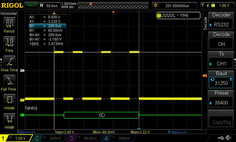
Above is pin 74 kicking out the value 0x6d that I manually wrote to register 9 via the debug command line interface in the librarian "term" mode (the command was "9 0x6d wr "). The baud rate is 1MHz/32 = 31.25kHz; the data is LSb first, one start bit and one stop bit. You can't see the stop bit here because it has the same low level as the following quiescent line non-activity, but we can measure the 9 bits and see that indeed 9/288us = 31.25kHz.
I know it was a long time ago, but why oh why did they pick such a slow and non-standard BAUD rate for MIDI? Why not 38400 at least? I mean, what were they thinking? They had a 1MHz processor and just wanted to kick out a byte every 32 cycles? Not that it matters to me all that much as it's just build parameters, but still, one bad engineering decision can cause untold mayhem for thousands of poor EEs for decades to come.
There are no current plans to do MIDI RX IN on the D-Lev, that would be a fairly huge undertaking requiring more cycles and memory that aren't available, not to mention an architectural overhaul that I'm not very interested in.
Anyway, I'm semi-stoked over this MIDI project! Need something to keep me off the streets...


