Let's Design and Build a (mostly) Digital Theremin!

Posted: 12/21/2014 4:17:06 PM
dewster

From: Northern NJ, USA

Joined: 2/17/2012

Been busy revisiting things that felt fairly unresolved. 

1. As I posted over on the analog thread, I took a bunch of data with various antenna geometries and stuck it in a spreadsheet with both analog and digital Theremin simulations:

http://www.mediafire.com/download/8qzfo3529j831if/Analog_Digital_2014-12-13.xls

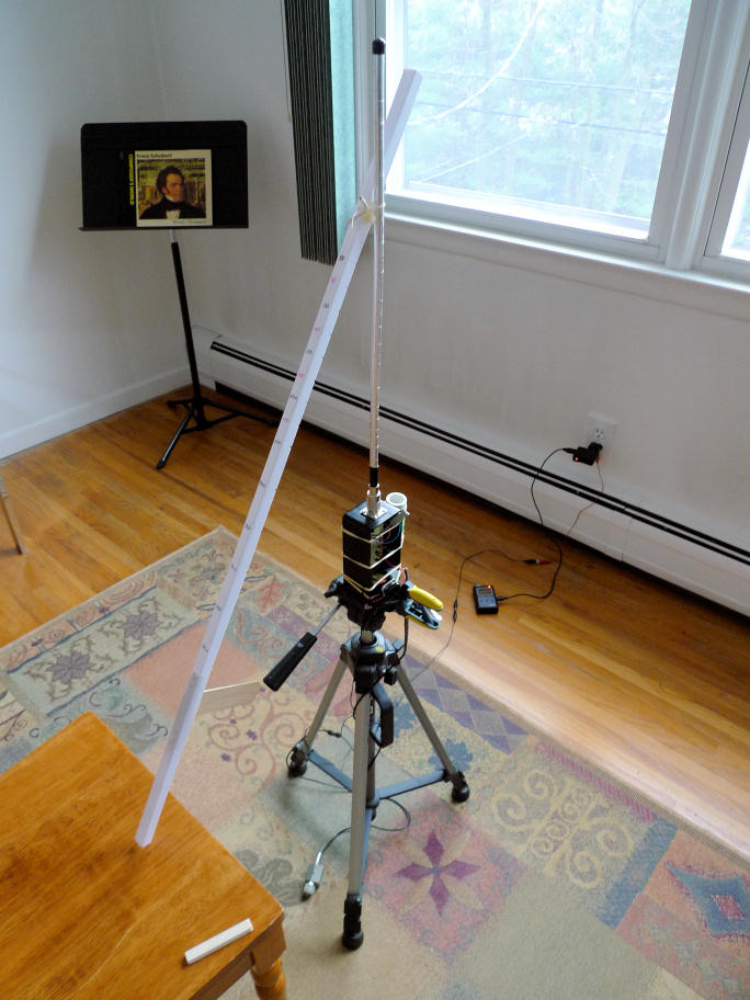
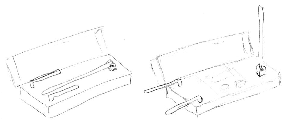
Above is my measuring apparatus with the measuring stick resting on the chair I sat in to take the data.  In use the stick rested on my shoulder, with the wooden piece sticking down from it against my shoulder to maintain constant distance between my body and the antenna.  There are notches in the bottom of the rod that let my thumb "feel" the test distances.  Tripod height was adjusted to make the measuring stick perpendicular to the antenna axis, checked with a small spirit level.  Grounded via mains outlet in the background, where the frequency counter is also charging.

A closer view of the oscillator.  Two NFETs on a plastic breadboard in a plastic box.  That's the 0.5mH air coil on the right held on with rubber bands.  Powered by 9V battery regulated down to 3.3V.

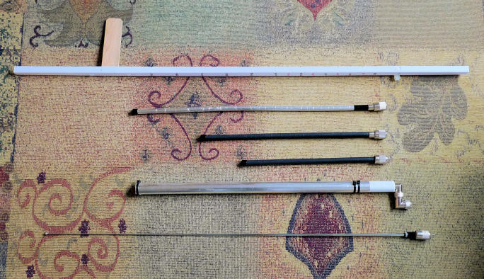
Above, from top to bottom: measuring stick, antenna #3, #2, #1, #4, #5 & #6 (whip was tested for two different lengths of extension).  Plate antenna #7 not shown.

I gave up on developing a predictive mutual capacitance formula.  The data for antenna 7 (a 235mm high x 115mm wide metal plate) is particularly interesting for digital Theremins.  Not surprisingly it is the most sensitive in absolute terms, and also looks the most linear when measuring the offset heterodyned period.  With a ~2.5MHz oscillator and a minimum of stray or pad C, the minimum far field heterodyne is around 200kHz, which is way above audio:

A plate would be somewhat directional as well.  I'm having trouble coming up with a good physical design for implementation.  Being able to rotate it about the vertical axis some would be good so that the player can orient it as they see fit.  The entire oscillator and coil could be incorporated into the antenna for maximum sensitivity, which would require a three wire connection (TRS audio jack?).  Insulating the antenna plate would likely be best from an ESD standpoint.  I'm wondering if PWB material would work, with the oscillator built on the same board?

==================

2. The period measurement (which is variable rate, the inter-sample timing directly proportional to the period itself) has constantly nagged me.  I thought a CIC filter was the best answer, but all those zeros in the transition zone seem like they could be trouble.  A simple IIR filter requires two wide adds in the same clock period which tends to limit top speed.  Yesterday I simulated a simple IIR with an extra register between the two adds (the output of which is actually the high pass response: input-lp=hp) which speeds it up:

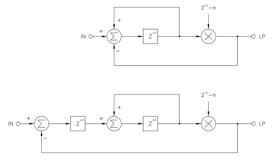
The normal IIR is shown at top, the "fast" IIR on the bottom.  Multiplication here is a simple, free, and instantaneous right bit shift by n.  For n>4 the response of both is almost identical.  For smaller n the "fast" version gets peaky.  I want to run it at the same speed as the processor - 160MHz - and with n=14 for a cutoff around 1kHz.  Cascading 4 of these 1st order stages gives ~80dB/decade and good transient response due to the low total Q:

The above shows that with this arrangement we can sample the output of this filter at the audio rate of 48kHz and expect no more than -95dB of aliasing, which should be entirely adequate if not total overkill.  This filter (including a small 1st order variable rate IIR filter before it) takes ~6% of the FPGA resources with excellent utilization of the logic consumed (LUTs & FFs).  Input data is 12 bits wide, output data is 32 bits wide.  Since we are going from a sample rate of 160MHz to 48kHz, the bit growth is log2(160/0.048)=11.7 or 12 bits, so the output has 32-12-12=8 bits of excess resolution we can likely just discard (or not calculate in the first place, reducing FPGA consumption to 5%).

Posted: 1/5/2015 9:18:10 AM
Pflogger

Joined: 1/5/2015

it is an inscrutable language. It's assembly language for a stack machine.


[url=http://www.hulle6.com/category-samsung-galaxy-alpha-zubehoer-125.html][color=#C9C9C9]samsung galaxy alpha hülle[/color][/url]

Posted: 1/11/2015 4:26:55 PM
dewster

From: Northern NJ, USA

Joined: 2/17/2012

Thinking about the left hand two axis configuration, where two antennas separated by a small distance sense the conventional proximity (Z axis), as well as the differential between them (Y axis). 

The simplest arrangement would be where one antenna is the "master" with its LC resonance driving the "slave" antenna/L.  The problem scenario with this is if someone touches the either antenna individually, thus lowering its resonance below the point where strong resonance can be maintained, producing a signal back to the FPGA that may be difficult or impossible to interpret once squared up. 

A better but more complex arrangement would be to use a DPLL in the FPGA, where separate phase detectors are used for each of the antenna/L assemblies, and the phase error average (or some other numerical concoction) is used to adjust the stimulus frequency.

In general, I think it is best to quite thickly insulate the antennae of any Theremin.  This would greatly help with the offset resonance scenarios above by limiting the capacitance change due to the hand when it touches the antenna, and would also largely mitigate the need for aggressive ESD measures.

I also think that removable antennae should perhaps not be the norm for newer Theremins.  This creates a physically weak point that also electrically exposes the internals to ESD during installation & removal.  Alternatives such as telescoping / folding / etc. should be investigated.  The volume antenna could perhaps be a conductive lined "hole" cut in the left top side of a longish non-conductive case.

Posted: 1/11/2015 6:46:38 PM
FredM

From: Eastleigh, Hampshire, U.K. ................................... Fred Mundell. ................................... Electronics Engineer. (Primarily Analogue) .. CV Synths 1974-1980 .. Theremin developer 2007 to present .. soon to be Developing / Trading as WaveCrafter.com . ...................................

Joined: 12/7/2007

Hi Dewster,

I agree with your insulation suggestion.

I dont however agree with the others ;-) ... ESD protection of the rod at the connector is easy to fit, telescopic / folding antennas with thick insulation and without any conductive areas accessible could be quite difficult to engineer.

As for the loop - despite the fact that people say its needed, I dont think it is... I think the Melodia shows the simplest and most effective alternative to a loop..

From what I can deduce about theremin players, they want a loop - but this needs to be a conventional loop.. If you dont give them this, you may as well give them the simple plate the Melodia uses.

Fred.

Posted: 1/12/2015 11:27:09 PM
dewster

From: Northern NJ, USA

Joined: 2/17/2012

"... telescopic / folding antennas with thick insulation and without any conductive areas accessible could be quite difficult to engineer."  - FredM

Ha!  I was wondering if anyone would catch that.  Insulated telescoping would be a problem.  But insulated folding might not be too difficult.  They make non-insulated pivoting bases for CB antennas, and something like the little hinge on most router wifi SMA antennas would work too.  Just make the case long enough to have the antenna fold down on top of the controls.  Maybe have the top hinged to cover it all up.

The wifi antenna mount also rotates, so the volume side might consist of two of these folded down and rotated in, then simply rotated out for use.  The hinged wifi antenna on my router seems to have a braided wire inside the hinge, not sure how many flexes it could take.  A weak spring here might be better than a wire.

Rough sketch:

Posted: 1/13/2015 4:58:44 PM
xtheremin8

From: züriCH

Joined: 3/15/2014

oh how i love sketches.  is the lid for cover? if so, you could make  the lid go flat down when opened, those two volume antennas then do not need to be hinged, only rotateable....do'h, just saw, you did not  sketch hinges for those two anyway! volume antenna: i thought that the antenna hinges are made of brass and so the conductive part, so that it does not need a extra wire/soft spring. (like telescopic radio antennas).. {but hey, as a volume plate antenna lover since ever, what can i say? plates are easier to design or to hide in the chassis. on the tmini, it's basically a plate antenna, with a hole. i guess, many theremin player just need the loop to get a grip on something real. like their anchor point in space and time.}

PlastiDip for insulation of existing antennas? 


Posted: 1/14/2015 12:02:16 AM
dewster

From: Northern NJ, USA

Joined: 2/17/2012

xtheremin8, PlastiDip is a good suggestion, I'll keep that in mind.  I'd kill to get a case that has either a removable lid or one that stays back at a 45 degree angle with some room inside for the tuner display.  Going with a plate under the top going to the left and down the side would likely be easier than the volume antennas.  I suppose if people aren't screaming too much about the Theremini volume side then just about anything goes.

Posted: 1/14/2015 4:13:46 PM
xtheremin8

From: züriCH

Joined: 3/15/2014

who would not kill for "the" box?  i guess you need more but just one? i once found a wooden 35mm slide box. for storing two rows of each 50 slides. nearly the dimensions and look of a etherwave. well, 10cm shorter, but that was long enough for my purposes. the lid is 2cm deep. enough for a display? that was a single finding and i needed to take out the inlays.

because i don't sleep much anyway, i found that one: chinese slide boxes . (no dimensions mentioned, but laboratory slides are rather small. so i think these are a bit more expensive: british tool-box . but i guess that something similar could be found in the states too. i thought you have once found a black-box case once?  i think, designing things is such a multidimensional task anyway. material, look, shape, size, functionality, colour, price, maybe the ethics of production, and more all counts in.

still my personal favorit: aero-plywood, 1mm with 3layers!  my "avataremin" is made with that: 3mm for bottom and the sides, 1mm for the curved surface. could easy be lasercutted and massproduced. naaa, the later is just kidding.  i simply like the look of alu and sycamore. and here comes the  factor: taste. and that is endless....:-)

Posted: 1/14/2015 8:23:47 PM
FredM

From: Eastleigh, Hampshire, U.K. ................................... Fred Mundell. ................................... Electronics Engineer. (Primarily Analogue) .. CV Synths 1974-1980 .. Theremin developer 2007 to present .. soon to be Developing / Trading as WaveCrafter.com . ...................................

Joined: 12/7/2007

"I'd kill to get a case that has either a removable lid or one that stays back at a 45 degree angle with some room inside for the tuner display. " - Dewster

One theremin I built (a quick knock-together based on the EPE-2008 I did for one of the people who played my H1 and wanted it with volume) used a hard pool cue case - the hinge was not strong enough so I replaced these with catches to make the 'lid' removable, and I used FR4 for the panel. The length of the case was ideal (volume sensor was a plate on this).

Posted: 1/15/2015 4:00:08 PM
dewster

From: Northern NJ, USA

Joined: 2/17/2012

Hi Fred,

Thanks!  I believe that's the Attache case 2647 from Peradon?  If so, the 34" length looks good, and the 5" width is about right, but the 2" depth is likely too shallow.  The FPGA board itself is ~1" deep when a ribbon cable is plugged into it, leaving little room for top and bottom case thickness, panel & knob height, etc.

You must be logged in to post a reply. Please log in or register for a new account.