Been busy revisiting things that felt fairly unresolved.
1. As I posted over on the analog thread, I took a bunch of data with various antenna geometries and stuck it in a spreadsheet with both analog and digital Theremin simulations:
http://www.mediafire.com/download/8qzfo3529j831if/Analog_Digital_2014-12-13.xls
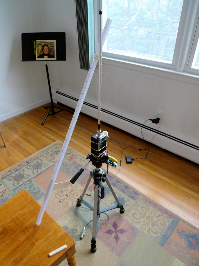
Above is my measuring apparatus with the measuring stick resting on the chair I sat in to take the data. In use the stick rested on my shoulder, with the wooden piece sticking down from it against my shoulder to maintain constant distance between my body and the antenna. There are notches in the bottom of the rod that let my thumb "feel" the test distances. Tripod height was adjusted to make the measuring stick perpendicular to the antenna axis, checked with a small spirit level. Grounded via mains outlet in the background, where the frequency counter is also charging.

A closer view of the oscillator. Two NFETs on a plastic breadboard in a plastic box. That's the 0.5mH air coil on the right held on with rubber bands. Powered by 9V battery regulated down to 3.3V.
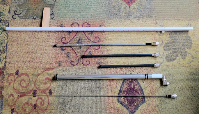
Above, from top to bottom: measuring stick, antenna #3, #2, #1, #4, #5 & #6 (whip was tested for two different lengths of extension). Plate antenna #7 not shown.
I gave up on developing a predictive mutual capacitance formula. The data for antenna 7 (a 235mm high x 115mm wide metal plate) is particularly interesting for digital Theremins. Not surprisingly it is the most sensitive in absolute terms, and also looks the most linear when measuring the offset heterodyned period. With a ~2.5MHz oscillator and a minimum of stray or pad C, the minimum far field heterodyne is around 200kHz, which is way above audio:
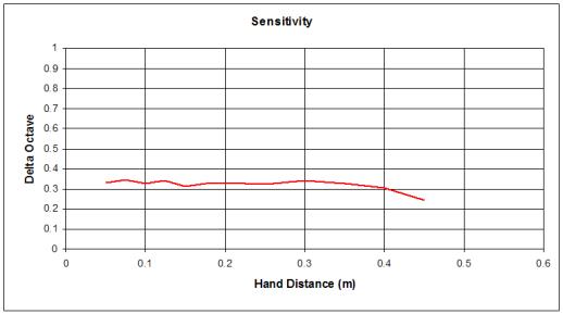
A plate would be somewhat directional as well. I'm having trouble coming up with a good physical design for implementation. Being able to rotate it about the vertical axis some would be good so that the player can orient it as they see fit. The entire oscillator and coil could be incorporated into the antenna for maximum sensitivity, which would require a three wire connection (TRS audio jack?). Insulating the antenna plate would likely be best from an ESD standpoint. I'm wondering if PWB material would work, with the oscillator built on the same board?
==================
2. The period measurement (which is variable rate, the inter-sample timing directly proportional to the period itself) has constantly nagged me. I thought a CIC filter was the best answer, but all those zeros in the transition zone seem like they could be trouble. A simple IIR filter requires two wide adds in the same clock period which tends to limit top speed. Yesterday I simulated a simple IIR with an extra register between the two adds (the output of which is actually the high pass response: input-lp=hp) which speeds it up:
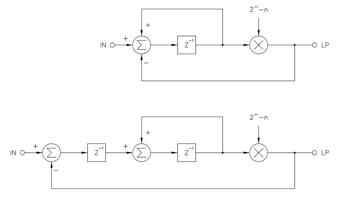
The normal IIR is shown at top, the "fast" IIR on the bottom. Multiplication here is a simple, free, and instantaneous right bit shift by n. For n>4 the response of both is almost identical. For smaller n the "fast" version gets peaky. I want to run it at the same speed as the processor - 160MHz - and with n=14 for a cutoff around 1kHz. Cascading 4 of these 1st order stages gives ~80dB/decade and good transient response due to the low total Q:

The above shows that with this arrangement we can sample the output of this filter at the audio rate of 48kHz and expect no more than -95dB of aliasing, which should be entirely adequate if not total overkill. This filter (including a small 1st order variable rate IIR filter before it) takes ~6% of the FPGA resources with excellent utilization of the logic consumed (LUTs & FFs). Input data is 12 bits wide, output data is 32 bits wide. Since we are going from a sample rate of 160MHz to 48kHz, the bit growth is log2(160/0.048)=11.7 or 12 bits, so the output has 32-12-12=8 bits of excess resolution we can likely just discard (or not calculate in the first place, reducing FPGA consumption to 5%).


